Dell PowerConnect W-IAP175P Installation Guide
Dell PowerConnect W-IAP175P Manual
 |
View all Dell PowerConnect W-IAP175P manuals
Add to My Manuals
Save this manual to your list of manuals |
Dell PowerConnect W-IAP175P manual content summary:
- Dell PowerConnect W-IAP175P | Installation Guide - Page 1
Guide The Dell PowerConnect W-IAP175 is a resilient, environmentally hardened, outdoor rated, dual-radio, dual-band IEEE 802.11 a/b/g/n wireless access point. This outdoor access point is part of Dell 12 provides instructions on weatherproofing networking functionality W-IAP175P: IEEE 802.3at - Dell PowerConnect W-IAP175P | Installation Guide - Page 2
Cable Installation Guide NOTE: Inform your supplier if there are any incorrect, missing, or damaged parts. If possible, retain the carton, including the original packing materials. Use these materials to repack and return the unit to the supplier if needed. 2 Dell PowerConnect W-IAP175 Outdoor - Dell PowerConnect W-IAP175P | Installation Guide - Page 3
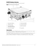
Overview (W-IAP175P shown) 5 6 4 3 7 8 2 1 1 Antenna Interface (Radio 1) 2 USB Console Interface 3 Reserved (W-IAP175P) or (Radio 1). R0 supports the 5 GHz frequency band and R1 supports the 2.4 GHz radio band. Dell PowerConnect W-IAP175 Outdoor Instant Access Point | Installation Guide 3 - Dell PowerConnect W-IAP175P | Installation Guide - Page 4
W-IAP175P: This IAP175P, this port also supports IEEE 802.3at Power over Ethernet (PoE), accepting 48 VDC as a standards-defined powered device (PD) from a power sourcing equipment (PSE) device, such as a PoE midspan 4 Dell PowerConnect W-IAP175 Outdoor Instant Access Point | Installation Guide - Dell PowerConnect W-IAP175P | Installation Guide - Page 5
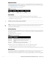
less than 5 ohm between the ground termination point and the grounding tier. W-IAP175P LED Status Indicators The W-IAP175 include visual indicators for power, link, and radio WLAN mode Blinking Air Monitor (AM) mode Dell PowerConnect W-IAP175 Outdoor Instant Access Point | Installation Guide 5 - Dell PowerConnect W-IAP175P | Installation Guide - Page 6
Table 3 W-IAP175P LED Status Indicators (Continued) LED RSSI (Radio 0) Function Indicator RSSI Level for Radio 0 Off 4 Step /Ready Off No power to AP Status Blinking Device booting, not ready On Device ready 6 Dell PowerConnect W-IAP175 Outdoor Instant Access Point | Installation Guide - Dell PowerConnect W-IAP175P | Installation Guide - Page 7
Successfully evaluating the environment enables the proper selection of Dell APs and antennas and assists in the determination of their placement for optimal RF coverage. This process is considered WLAN or RF planning. Dell PowerConnect W-IAP175 Outdoor Instant Access Point | Installation Guide 7 - Dell PowerConnect W-IAP175P | Installation Guide - Page 8
achieve results similar to an indoor deployment: a "dense" RF deployment that supports advanced Aruba features, such as ARM, efficient client roaming, and failover. illustrates the concept of a good radio line of sight. 8 Dell PowerConnect W-IAP175 Outdoor Instant Access Point | Installation Guide - Dell PowerConnect W-IAP175P | Installation Guide - Page 9
(1.9 m) 8.9 ft (2.7 m) 12.5 ft (3.8 m) 15.4 ft (4.7 m) 0.007 ft (0.002 m) 0.03 ft (0.010 m) 0.13 ft (0.04 m) 0.5 ft (0.15 m) 1.0 ft (0.3 m) 4.6 ft (1.4 m) 6.2 ft (1.9 m) 8.9 ft (2.7 m) 13.1 ft (4.0 m) 16.4 ft (5.0 m) Dell PowerConnect W-IAP175 Outdoor Instant Access Point | Installation Guide 9 - Dell PowerConnect W-IAP175P | Installation Guide - Page 10
of a high radio mast or tower. If your wireless bridge or mesh link requires a high radio mast or tower, consult a professional contractor for advice. 10 Dell PowerConnect W-IAP175 Outdoor Instant Access Point | Installation Guide - Dell PowerConnect W-IAP175P | Installation Guide - Page 11
signal. If radio interference is still a problem with your wireless bridge or mesh link, velocity and direction at the site and be sure that any supporting structure, such as a pole, mast, or tower, is applicable). Dell PowerConnect W-IAP175 Outdoor Instant Access Point | Installation Guide 11 - Dell PowerConnect W-IAP175P | Installation Guide - Page 12
is important that the wireless bridge or mesh link, cables, and any supporting structures are properly grounded. Each W-IAP175 access point includes a grounding screw connected antennas, see "Weatherproofing Directly 12 Dell PowerConnect W-IAP175 Outdoor Instant Access Point | Installation Guide - Dell PowerConnect W-IAP175P | Installation Guide - Page 13
, see "Weatherproofing Cable Connections" on page 18. NOTE: The following instructions assume that you have installed a lightning arrestor on your W-IAP175. Figure 6 Directly Connected Antennas Weep holes AP175_11 Dell PowerConnect W-IAP175 Outdoor Instant Access Point | Installation Guide 13 - Dell PowerConnect W-IAP175P | Installation Guide - Page 14
, make the each layer of tape as flat as possible. Wrinkles and folds in the tape create places for water and moisture to gather. 14 Dell PowerConnect W-IAP175 Outdoor Instant Access Point | Installation Guide - Dell PowerConnect W-IAP175P | Installation Guide - Page 15
Weatherproofing Directly Connected Antennas NOTE: The following instructions assume that you have installed a lightning arrestor between your W-IAP175. First Wrap first layer of tape reversed: sticky side out AP175_12 Dell PowerConnect W-IAP175 Outdoor Instant Access Point | Installation Guide 15 - Dell PowerConnect W-IAP175P | Installation Guide - Page 16
rubber around base of antenna mount and lightning arrestor Squeeze to bond rubber to itself Rubber will be wrapped with 4 layers of tape AP175_14 16 Dell PowerConnect W-IAP175 Outdoor Instant Access Point | Installation Guide - Dell PowerConnect W-IAP175P | Installation Guide - Page 17
of tape AP175_15 First and third layers wrap top to bottom 4. Repeat this process for all connectors. Second and final layers wrap bottom to top Dell PowerConnect W-IAP175 Outdoor Instant Access Point | Installation Guide 17 - Dell PowerConnect W-IAP175P | Installation Guide - Page 18
to the cable's insulation. Figure 12 First Wrapping of Tape Wrap tape from antenna connector base to cable Pieces of tape as needed AP175_17 18 Dell PowerConnect W-IAP175 Outdoor Instant Access Point | Installation Guide - Dell PowerConnect W-IAP175P | Installation Guide - Page 19
14 Butyl Rubber Wrap Wrap rubber around connector and cable Squeeze to bond rubber to itself Rubber will be wrapped with 4 layers of tape AP175_19 Dell PowerConnect W-IAP175 Outdoor Instant Access Point | Installation Guide 19 - Dell PowerConnect W-IAP175P | Installation Guide - Page 20
the network planning and technical requirements of communications equipment, as well as the considerations such as climate, hydrology, geology, earthquake, electric power, and transportation. 20 Dell PowerConnect W-IAP175 Outdoor Instant Access Point | Installation Guide - Dell PowerConnect W-IAP175P | Installation Guide - Page 21
x110 bolts (with flat washers, spring washers and nuts) and the pair of pole anchors. Figure 17 Attaching the mounting bracket to the pole AP175_03 Dell PowerConnect W-IAP175 Outdoor Instant Access Point | Installation Guide 21 - Dell PowerConnect W-IAP175P | Installation Guide - Page 22
to the mounting bracket by inserting the two M6 x30 bolts (with flat and spring washers) through the installation holes, and tighten the bolts. 22 Dell PowerConnect W-IAP175 Outdoor Instant Access Point | Installation Guide - Dell PowerConnect W-IAP175P | Installation Guide - Page 23
firmly with the crimping pliers. 2. Fasten the copper lug to the grounding hole on the W-IAP175 with the M4 x12 bolt and external-tooth washer. Dell PowerConnect W-IAP175 Outdoor Instant Access Point | Installation Guide 23 - Dell PowerConnect W-IAP175P | Installation Guide - Page 24
Connecting the Ethernet Cable (W-IAP175P) To ensure that your outdoor access point (AP) maintains ethernet connectivity and Power over 11. Water-proof the ethernet cable connection with electrical tape and butyl rubber. 24 Dell PowerConnect W-IAP175 Outdoor Instant Access Point | Installation Guide - Dell PowerConnect W-IAP175P | Installation Guide - Page 25
ethernet cable connector into the ethernet interface and hand-tighten the locknut. 15. Water-proof the ethernet cable connection with electrical tape and butyl rubber. Dell PowerConnect W-IAP175 Outdoor Instant Access Point | Installation Guide 25 - Dell PowerConnect W-IAP175P | Installation Guide - Page 26
(W-IAP175 AC) CAUTION: Installation and service of Dell products should be performed by Professional AC power interface. Assembly instructions for this part are shipped with the part. All instructions must be followed to Dell PowerConnect W-IAP175 Outdoor Instant Access Point | Installation Guide - Dell PowerConnect W-IAP175P | Installation Guide - Page 27
to the W-IAP175 by using the four M4 x16 (with flat and spring washers). Figure 25 Attaching the Solar Shield to the AP AP175_08 AP175_07 Dell PowerConnect W-IAP175 Outdoor Instant Access Point | Installation Guide 27 - Dell PowerConnect W-IAP175P | Installation Guide - Page 28
support (supports MIMO) Feeder cable may be used for external antenna deployments Visual Status Indicators (LEDs): See Table 3 Electrical Power In W-IAP175P antenna interfaces Other: 1 x USB console interface 28 Dell PowerConnect W-IAP175 Outdoor Instant Access Point | Installation Guide - Dell PowerConnect W-IAP175P | Installation Guide - Page 29
(Mbps): 802.11b: 1, 2, 5.5, 11 802.11a/g: 6, 9, 12, 18, 24, 36, 48, 54 802.11n: MCS0 - MCS15 (6.5 Mbps to 300 Mbps) 802.11n high-throughput (HT) support: HT 20/40 802.11n packet aggregation: A-MPDU, A-MSDU Dell PowerConnect W-IAP175 Outdoor Instant Access Point | Installation Guide 29 - Dell PowerConnect W-IAP175P | Installation Guide - Page 30
and, if not installed and used in accordance with the instructions, may cause harmful interference to radio communications. However, there is Country Specific Regulations please speak with your Dell Representative. 30 Dell PowerConnect W-IAP175 Outdoor Instant Access Point | Installation Guide - Dell PowerConnect W-IAP175P | Installation Guide - Page 31
left indicating conformance to this Directive. China RoHS Dell products also comply with China environmental declaration requirements and are labeled with the "EFUP 25" label shown at the left. Singapore 200202320G Dell PowerConnect W-IAP175 Outdoor Instant Access Point | Installation Guide 31 - Dell PowerConnect W-IAP175P | Installation Guide - Page 32
UAE (W-IAP175P) TRA REGISTERED No: ER0055290/11 DEALER No: DA0039425/10 UAE (W-IAP175AC) TRA REGISTERED No: ER0082364/12 DEALER No: DA0039425/10 Contacting Support Website Support Main Website Support Website Dell Documentation dell.com support.dell.com support.dell.com/manuals Copyright © 2012
-
 1
1 -
 2
2 -
 3
3 -
 4
4 -
 5
5 -
 6
6 -
 7
7 -
8
-
9
-
10
-
11
-
12
-
13
-
14
-
15
-
16
-
17
-
18
-
19
-
20
-
21
-
22
-
23
-
24
-
25
-
26
-
27
-
28
-
29
-
30
-
31
-
32
 |
 |
Dell PowerConnect W-IAP175 Outdoor Instant Access Point
Installation Guide
0511155-01
| September 2012
1
The Dell PowerConnect W-IAP175 is a resilient, environmentally hardened, outdoor rated, dual-radio, dual-band
IEEE 802.11 a/b/g/n wireless access point. This outdoor access point is part of Dell’s comprehensive wireless
network solution.
There are three versions of the W-IAP175, which mainly differ in the way they receive power.
W-IAP175P: PoE+ powered (802.3at)
W-IAP175AC: AC powered (100-240 V AC)
Guide Overview
“W-IAP175 Hardware Overview” on page
3
provides a detailed hardware overview of the three W-IAP175
models.
“Outdoor Planning and Deployment Considerations” on page
7
provides key questions to ask and items to
consider when deploying an outdoor wireless network.
“Installing Antennas” on page
12
describes how to installing antennas.
“Weatherproofing Connections” on page
12
provides instructions on weatherproofing the AP’s connectors.
“Installing the W-IAP175” on page
20
describes the multi-step process for a successful installation and
deployment of an W-IAP175.
“Safety and Regulatory Compliance” on page
30
provides an overview of safety and regulatory compliance
information.
W-IAP175 Operations
Wireless access point (IEEE 802.11 a/b/g/n)
Wireless air monitor (IEEE 802.11 a/b/g/n)
Enterprise mesh point
Enterprise mesh portal
Protocol-independent networking functionality
W-IAP175P: IEEE 802.3at Power over Ethernet+ (PoE+) compatible
W-IAP175AC: IEEE 802.3af Power Sourcing Equipment (PSE) device
NOTE:
The W-IAP175 requires Instant 3.0 or later.
NOTE:
The W-IAP175AC can function as a Power Sourcing Equipment (PSE) device by providing power through its ethernet port in
compliance with the IEEE 802.3af standard.