Dell PowerConnect W-IAP175P Installation Guide - Page 7
Outdoor Planning and Deployment Considerations
 |
View all Dell PowerConnect W-IAP175P manuals
Add to My Manuals
Save this manual to your list of manuals |
Page 7 highlights
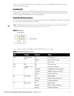
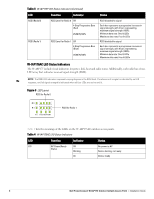
Table 4 W-IAP175AC LED Status Indicators (Continued) LED Function Indicator Status POE Heat ENT R0 R1 RSSI (Radio 0) RSSI (Radio 1) Displays PSE power Off output status Non-powered device (0Ω
-
 1
1 -
 2
2 -
 3
3 -
 4
4 -
 5
5 -
 6
6 -
 7
7 -
 8
8 -
 9
9 -
 10
10 -
 11
11 -
 12
12 -
13
-
14
-
15
-
16
-
17
-
18
-
19
-
20
-
21
-
22
-
23
-
24
-
25
-
26
-
27
-
28
-
29
-
30
-
31
-
32
 |
 |

Dell PowerConnect W-IAP175 Outdoor Instant Access Point
|
Installation Guide
7
Outdoor Planning and Deployment Considerations
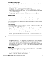
Prior to deploying an outdoor wireless network, the environment must be evaluated to plan for a successful Dell
WLAN deployment. Successfully evaluating the environment enables the proper selection of Dell APs and
antennas and assists in the determination of their placement for optimal RF coverage. This process is considered
WLAN or RF planning.
POE
Displays PSE power
output status
Off
Non-powered device (0
Ω
<Rport<200
Ω
) or Port
open (Rport>1M
Ω
)
Green
Port on (25k
Ω
)
1 Flash: Low signature resistance
(300
Ω
<Rport<15k
Ω
)
2 Flashes: High signature resistance
(33k
Ω
<Rport<500k
Ω
)
5 Flashes: Port overload fault
9 Flashes: Power management allocation
exceeded
Heat
Displays the heating
status of low
temperature
Off
Unit is not in heating status
Blinking (Blue)
Unit is pre-heating
ENT
LAN/Network Link
Status
Off
Ethernet link unavailable
On (Amber)
10/100 Mbs ethernet link negotiated
On (Green)
1000 Mbs ethernet link negotiated
Blinking
Traffic on ethernet link
R0
Radio 0 Status
Off
Radio 0 disabled
On (Amber)
Radio 0 enabled in WLAN mode
Blinking
Air Monitor (AM) mode
R1
Radio 1 Status
Off
Radio 1disabled
On (Blue)
Radio 1 enabled in WLAN mode
Blinking
Air Monitor (AM) mode
RSSI (Radio 0)
RSSI Level for Radio 0
Off
RSSI disabled/no signal
4 Step Progressive Bars
(Red)
25/50/75/100%
Each bar represents a progressive increase in
signal strength, with 4 bars representing maximum
signal strength (100%).
Minimum data rate: One lit LEDs
Maximum data rate: Four lit LEDs
RSSI (Radio 1)
RSSI Level for Radio 1
Off
RSSI disabled/no signal
4 Step Progressive Bars
(Blue)
25/50/75/100%
Each bar represents a progressive increase in
signal strength, with 4 bars representing maximum
signal strength (100%).
Minimum data rate: One lit LEDs
Maximum data rate: Four lit LEDs
Table 4
W-IAP175AC LED Status Indicators (Continued)
LED
Function
Indicator
Status