Dell PowerConnect W-IAP175P Installation Guide - Page 5
Grounding Point, W-IAP175P LED Status Indicators, Function, Indicator, Status
 |
View all Dell PowerConnect W-IAP175P manuals
Add to My Manuals
Save this manual to your list of manuals |
Page 5 highlights
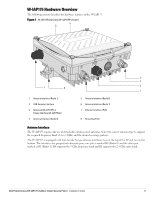
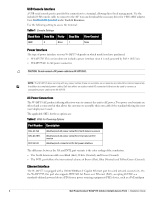
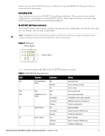
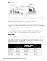
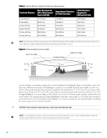
injector. Inversely, the W-IAP175AC can act as a PSE device to provide IEEE802.3af PoE power to devices connected to the ethernet port. Grounding Point Always remember to protect your W-IAP175 by installing grounding lines. The ground connection must be complete before connecting power to the W-IAP175 enclosure. Ensure that the resistance is less than 5 ohm between the ground termination point and the grounding tier. W-IAP175P LED Status Indicators The W-IAP175 include visual indicators for power, link, and radio status. Additionally, each radio has a four-LED array that indicates received signal strength (RSSI). NOTE: The RSSI LED indicators represent varying degrees in the RSSI level. The absence of a signal is indicated by no LED response, and full signal strength is indicated when all four LEDs are active and lit. Figure 2 LED Layout RSSI for Radio 0 P/S POE ENT RSSI for Radio 1 Table 3 lists the meanings of the LEDs on the W-IAP175P outdoor access point. Table 3 W-IAP175P LED Status Indicators LED Function Indicator Status P/S AP Power/Ready Off No power to AP Status Blinking Device booting, not ready On Device ready POE N/A N/A Not currently used ENT LAN/Network Link Off Ethernet link unavailable Status On (Amber) 10/100 Mbs ethernet link negotiated On (Green) 1000 Mbs ethernet link negotiated Blinking Traffic on ethernet link R0 Radio 0 Status Off Radio 0 disabled On (Amber) Radio 0 enabled in WLAN mode Blinking Air Monitor (AM) mode R1 Radio 1 Status Off Radio 1disabled On (Blue) Radio 1 enabled in WLAN mode Blinking Air Monitor (AM) mode Dell PowerConnect W-IAP175 Outdoor Instant Access Point | Installation Guide 5
-
 1
1 -
 2
2 -
 3
3 -
 4
4 -
 5
5 -
 6
6 -
 7
7 -
 8
8 -
 9
9 -
 10
10 -
 11
11 -
12
-
13
-
14
-
15
-
16
-
17
-
18
-
19
-
20
-
21
-
22
-
23
-
24
-
25
-
26
-
27
-
28
-
29
-
30
-
31
-
32
 |
 |
