Dell PowerConnect W-IAP175P Installation Guide - Page 8
Scale Requirements, Identifying Known RF Absorbers/Reflectors/Interferences Sources, RF Absorbers
 |
View all Dell PowerConnect W-IAP175P manuals
Add to My Manuals
Save this manual to your list of manuals |
Page 8 highlights
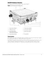
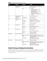
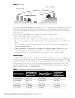
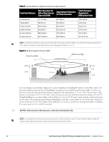
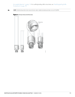
Scale Requirements The potentially immense scale of outdoor deployments requires consideration of factors that may not be as important in a typical indoor deployment: Range (distance): Range or distance between APs must be taken into account during the planning phase. Available AP mounting locations are often far less flexible in an outdoor environment. Regardless of these outdoor restrictions, the desired goal is to achieve results similar to an indoor deployment: a "dense" RF deployment that supports advanced Aruba features, such as ARM, efficient client roaming, and failover. Elevation: Proper consideration and planning for elevation differences between APs (AP to AP) and AP to Client can be critical to success. To plan for these differences in elevation, it is important to understand the 3D coverage pattern provided by the antennas that will be deployed in the environment. Non-Fixed Considerations: The RF environment might change on a day to day basis. Keep non-fixed items, such as shipping containers, vehicles, and future building construction, in mind when planning for an outdoor deployment. Identifying Known RF Absorbers/Reflectors/Interferences Sources Identifying known RF absorbers/reflectors/interference sources while out in the field during the installation phase is critical. Even though outdoor environments consist of fewer RF absorbers/reflectors/interference sources compared to indoor environments, ensure that these sources are identified and taken into consideration when installing and mounting an AP to its fixed outdoor location. RF Absorbers Cement/Concrete Natural Items: Trees/vegetation Brick RF Reflectors Metal Objects: Roof-installed air-conditioning equipment, chain link fences (depending on aperture size), other wire fences, or water pipes RF Interference Sources Other 802.11a/b/g/n or broadband access equipment operating nearby Industrial RF welding equipment or other Industrial, Scientific and Medical (ISM) equipment that utilizes RF to heat or alter the physical properties of materials Military, Commercial Aviation or Weather Radar Systems Line of Sight (Radio Path Planning) A wireless bridge or mesh link requires a "radio line of sight" between the two antennas for optimum performance. The concept of radio line of sight involves the area along a link through which the bulk of the radio signal power travels. This area is known as the first Fresnel Zone of the radio link. For a radio link, no object (including the ground) must intrude within 60% of the first Fresnel Zone. Figure 4 illustrates the concept of a good radio line of sight. 8 Dell PowerConnect W-IAP175 Outdoor Instant Access Point | Installation Guide
-
 1
1 -
2
-
 3
3 -
 4
4 -
 5
5 -
 6
6 -
 7
7 -
 8
8 -
 9
9 -
 10
10 -
 11
11 -
 12
12 -
 13
13 -
14
-
15
-
16
-
17
-
18
-
19
-
20
-
21
-
22
-
23
-
24
-
25
-
26
-
27
-
28
-
29
-
30
-
31
-
32
 |
 |
