Dell PowerConnect W-IAP175P Installation Guide - Page 9
Antenna Height, Table 5
 |
View all Dell PowerConnect W-IAP175P manuals
Add to My Manuals
Save this manual to your list of manuals |
Page 9 highlights
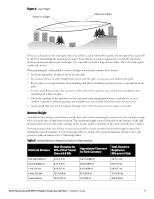
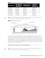
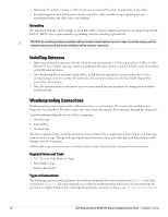
Figure 4 Line of Sight Visual Line of Sight Radio Line of Sight If there are obstacles in the radio path, there may still be a radio link but the quality and strength of the signal will be affected. Calculating the maximum clearance from objects on a path is important as it directly affects the decision on antenna placement and height. It is especially critical for long-distance links, where the radio signal could easily be lost. When planning the radio path for a wireless bridge or mesh link, consider these factors: Avoid any partial line of sight between the antennas Be cautious of trees or other foliage that may be near the path, or may grow and obstruct the path. Be sure there is enough clearance from buildings and that no building construction may eventually block the path. For very long distance links, the curvature of the earth (20 cm per km) may need to be considered in the calculation of relative heights. Check the topology of the land between the antennas using topographical maps, aerial photos, or even satellite image data (software packages are available that may include this information for your area) Avoid a path that may incur temporary blockage due to the movement of cars, trains, or aircraft. Antenna Height A reliable wireless bridge or mesh link is usually best achieved by mounting the antennas at each end high enough for a clear radio line of sight between them. The minimum height required depends on the distance of the link, obstacles that may be in the path, topology of the terrain, and the curvature of the earth (for links over 3 miles). For long-distance links, the AP may have to be mounted on masts or poles that are tall enough to attain the minimum required clearance. Use the following table to estimate the required minimum clearance above the ground or path obstruction (for 5 GHz bridge links). Table 5 Antenna Minimum Height and Clearance Requirements Total Link Distance Max Clearance for 60% of First Fresnel Zone at 5.8 GHz Approximate Clearance for Earth Curvature Total Clearance Required at Mid-point of Link 0.25 mile (0.402 km) 0.5 mile (0.805 km) 1 mile (1.6 km) 2 miles (3.2 km) 3 miles (4.8 km) 4.6 ft (1.4 m) 6.2 ft (1.9 m) 8.9 ft (2.7 m) 12.5 ft (3.8 m) 15.4 ft (4.7 m) 0.007 ft (0.002 m) 0.03 ft (0.010 m) 0.13 ft (0.04 m) 0.5 ft (0.15 m) 1.0 ft (0.3 m) 4.6 ft (1.4 m) 6.2 ft (1.9 m) 8.9 ft (2.7 m) 13.1 ft (4.0 m) 16.4 ft (5.0 m) Dell PowerConnect W-IAP175 Outdoor Instant Access Point | Installation Guide 9
-
 1
1 -
2
-
3
-
 4
4 -
 5
5 -
 6
6 -
 7
7 -
 8
8 -
 9
9 -
 10
10 -
 11
11 -
 12
12 -
 13
13 -
 14
14 -
15
-
16
-
17
-
18
-
19
-
20
-
21
-
22
-
23
-
24
-
25
-
26
-
27
-
28
-
29
-
30
-
31
-
32
 |
 |
