Dell PowerEdge XL 5133-4 Dell PowerEdge M I/O Aggregator Getting Started Guide - Page 15
Installation, Site Preparation
 |
View all Dell PowerEdge XL 5133-4 manuals
Add to My Manuals
Save this manual to your list of manuals |
Page 15 highlights
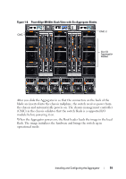
Table 1-3 describes the LED status of a 40GbE QSFP+ port that is split into four 10GbE SFP+ ports using a 4x10GbE breakout cable. Table 1-3. LED Status of 4x10GbE Port Port LED Link Status Color Off Yellow Activity Off Blinking Green Meaning All four 10GbE ports on a breakout cable are down. At least one of the four 10GbE ports on a breakout cable is up. No traffic is being transmitted on any 10GbE port on the breakout cable. Traffic is being transmitted or received on at least one of the 10GbE ports on the breakout cable. Installation Site Preparation Before installing the switch or switches, ensure that the chosen installation location meets the following site requirements: • Clearance - There is adequate front and rear clearance for operator access. Allow clearance for cabling, power connections, and ventilation. • Cabling - The cabling is routed to avoid sources of electrical noise such as radio transmitters, broadcast amplifiers, power lines, and fluorescent lighting fixtures. • Ambient Temperature - The ambient switch operating temperature range is 10° to 40ºC (50° to 104ºF). NOTE: Decrease the maximum temperature by 1°C (1.8°F) per 300 m (985 ft.) above 900 m (2955 ft.). • Relative Humidity - The operating relative humidity is 8% to 85% (noncondensing) with a maximum humidity gradation of 10% per hour. Hardware Overview 15
-
 1
1 -
2
-
3
-
4
-
5
-
6
-
7
-
8
-
9
-
 10
10 -
 11
11 -
 12
12 -
 13
13 -
 14
14 -
 15
15 -
 16
16 -
 17
17 -
 18
18 -
 19
19 -
 20
20 -
21
-
22
-
23
-
24
-
25
-
26
-
27
-
28
-
29
-
30
-
31
-
32
-
33
-
34
-
35
-
36
-
37
-
38
 |
 |
