Dell PowerEdge XL 5133-4 Dell PowerEdge M I/O Aggregator Getting Started Guide - Page 19
PowerEdge M1000e: Back View with Six Aggregator Blades, When the Aggregator powers
 |
View all Dell PowerEdge XL 5133-4 manuals
Add to My Manuals
Save this manual to your list of manuals |
Page 19 highlights
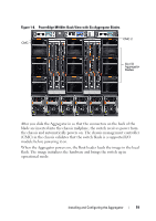
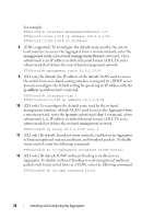
Figure 1-8. PowerEdge M1000e: Back View with Six Aggregator Blades CMC 1 CMC 2 Six I/O Aggregator blades After you slide the Aggregator in so that the connectors on the back of the blade are inserted into the chassis midplane, the switch receives power from the chassis and automatically powers on. The chassis management controller (CMC) in the chassis validates that the switch blade is a supported I/O module before powering it on. When the Aggregator powers on, the Boot loader loads the image in the local flash. The image initializes the hardware and brings the switch up in operational mode. Installing and Configuring the Aggregator 19
-
 1
1 -
2
-
3
-
4
-
5
-
6
-
7
-
8
-
9
-
10
-
11
-
12
-
13
-
 14
14 -
 15
15 -
 16
16 -
 17
17 -
 18
18 -
 19
19 -
 20
20 -
 21
21 -
 22
22 -
 23
23 -
 24
24 -
25
-
26
-
27
-
28
-
29
-
30
-
31
-
32
-
33
-
34
-
35
-
36
-
37
-
38
 |
 |

Installing and Configuring the Aggregator
19
Figure 1-8.
PowerEdge M1000e: Back View with Six Aggregator Blades
After you slide the Aggregator in so that the connectors on the back of the
blade are inserted into the chassis midplane, the switch receives power from
the chassis and automatically powers on. The chassis management controller
(CMC) in the chassis validates that the switch blade is a supported I/O
module before powering it on.
When the Aggregator powers on, the Boot loader loads the image in the local
flash. The image initializes the hardware and brings the switch up in
operational mode.
Six I/O
Aggregator
blades
CMC 1
CMC 2