Dewalt DW074KD Instruction Manual - Page 12
Using the Laser with a Wall Mount, Fig. 12 - level
 |
View all Dewalt DW074KD manuals
Add to My Manuals
Save this manual to your list of manuals |
Page 12 highlights
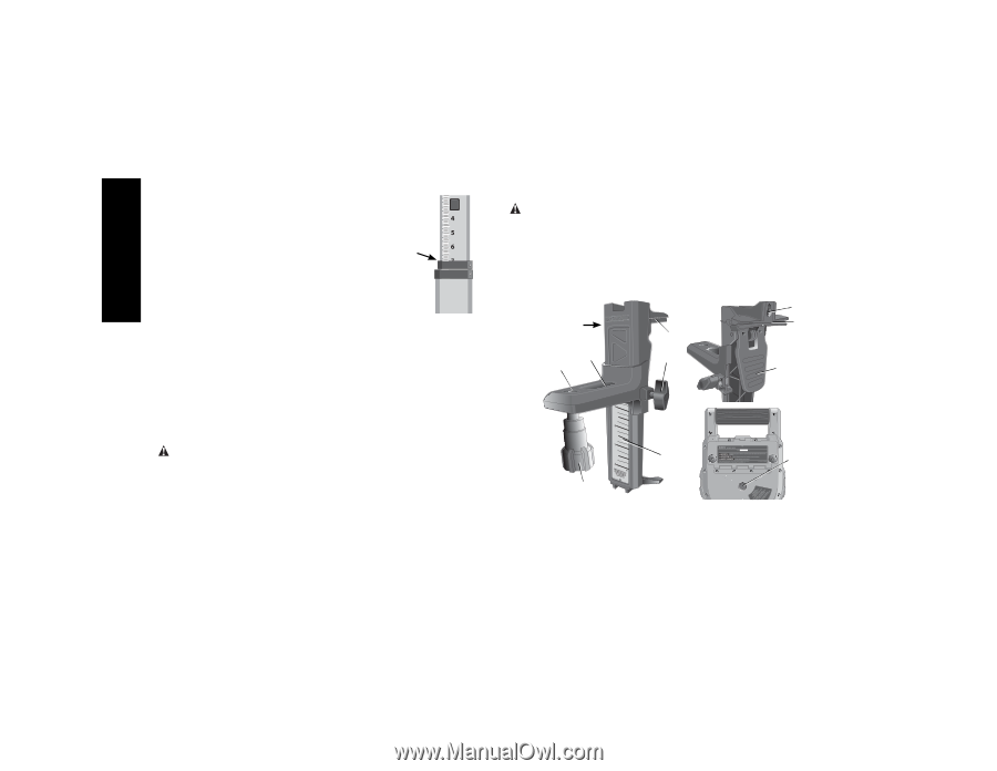
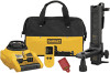
English in telescoping sections. A spring-loaded button FIG. 11 actuates a lock to hold the grade rod at various lengths. The front of the grade rod has the measurement scale starting at the bottom. Use this for measuring from the ground up when grading or leveling jobs. The back of the grade rod is designed to measure the height of ceilings, joists, etc. Fully extend the top section of the grade rod until the button locks into the previous section. Extend that section either until it locks into the adjacent section or until the grade rod touches the ceiling or joist. The height is read where the last extended section exits the previous lower section, as shown in Figure 11. Using the Laser with a Wall Mount (Fig. 12) Some laser kits include a Wall Mount. It can be used for attaching the tool to track or ceiling angle and to aid in acoustical ceiling installation. Follow the directions below for using the wall mount. CAUTION: Before attaching the laser level to wall track or ceiling angle, be sure that the track or angle is properly secured. 1. Place the laser on the mounting base (X) aligning the hole (Y) on the bottom of the laser with the hole (Z) in the mounting base. Place rear rubber foot into the mounting base slot (AA). Turn the mounting knob (BB) to secure the laser. 2. With the wall mount measuring scale (CC) facing you, push the clamp lever (DD) in to open the clamp jaws (EE). 3. Position the clamp jaws (EE) around the wall track or ceiling angle and release the clamp lever (DD) to close the clamp jaws on the track. Be sure that the wall mount is secure before proceeding. CAUTION: Always use a ceiling wire hanger or equivalent material, in addition to the wall mount clamp locking knob, to help secure the laser level while mounting it to a wall. Thread the wire through the handle of the laser level. DO NOT thread the wire through the protective roll cage. Additionally, screws may be used to fasten the wall mount directly to the wall as a back up. A screw holes (FF) is located at the top of the wall mount. FIG. 12 FF X EE EE AA GG Z DD CC Y BB 4. The tool can be adjusted up and down to the desired offset height for working. To change the height, loosen the locking knob (GG) located on the side of the wall mount to move the laser level up and down to the desired height. Support the mounting base when adjusting the height. 10
-
 1
1 -
2
-
3
-
4
-
5
-
6
-
 7
7 -
 8
8 -
 9
9 -
 10
10 -
 11
11 -
 12
12 -
 13
13 -
 14
14 -
 15
15 -
 16
16 -
 17
17 -
18
-
19
-
20
-
21
-
22
-
23
-
24
-
25
-
26
-
27
-
28
-
29
-
30
-
31
-
32
-
33
-
34
-
35
-
36
-
37
-
38
-
39
-
40
-
41
-
42
-
43
-
44
-
45
-
46
-
47
-
48
 |
 |