Dewalt DW074KD Instruction Manual - Page 14
Total Error = AA - A - BB- B, Distance between walls, Allowable Error, LEVEL CALIBRATION CHECK Y-
 |
View all Dewalt DW074KD manuals
Add to My Manuals
Save this manual to your list of manuals |
Page 14 highlights
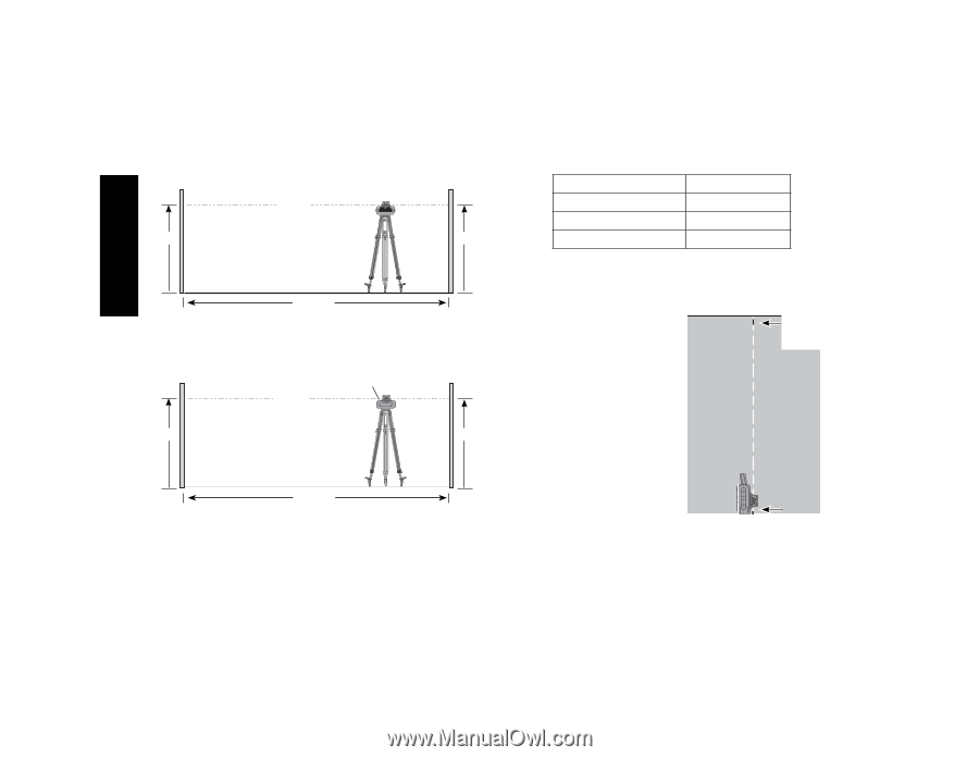
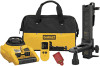
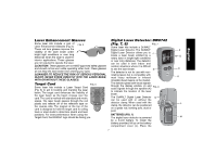
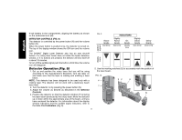
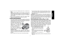
FIG. 15 A BEAM Distance between walls Allowable Error L = 50 ft. (15.3 m) 1/4" (6 mm) L = 75 ft. (22.9 m) 3/8" (9 mm) B L = 100 ft. (30.5 m) 1/2" (12 mm) English L 5. Turn the entire laser unit 180º so the X-axis points directly toward the opposite wall. 6. Allow the laser unit to self-level, and mark and measure points AA and BB on the walls as shown in Figure 16. FIG. 16 LASER UNIT ROTATED 180˚ BEAM AA BB L 7. Calculate the total error using the equation: Total Error = (AA - A) - (BB- B) 8. Compare total error to the allowable limits shown in the following table. LEVEL CALIBRATION CHECK (Y-AXIS) Repeat the procedure above, but with the laser unit positioned so the Y-axis is pointed directly toward the walls. PLUMB ERROR CHECK (FIG. 17) FIG. 17 1. Using a standard plumb bob as a reference, mark the top and bottom of a wall (Be sure to MARKS ON WALLS mark the wall and not the floor and ceiling.) 2. Position the rotary laser securely on the floor approximately 1 m (3 ft.) from the wall. 3. Turn the laser on and level it using the arrow buttons to center the bubble. Put the unit in low speed rotation for maximum vis- ibility, making sure the beam passes through the mark on the bottom of the wall. Recheck the bubble position to confirm it is still centered. 4. If the center of the beam lines up with the marks at the bottom and top of the wall, the laser is properly calibrated. NOTE: This check should be done with a wall no shorter than the tallest wall for which this laser will be used. 12
-
 1
1 -
2
-
3
-
4
-
5
-
6
-
7
-
8
-
 9
9 -
 10
10 -
 11
11 -
 12
12 -
 13
13 -
 14
14 -
 15
15 -
 16
16 -
 17
17 -
 18
18 -
 19
19 -
20
-
21
-
22
-
23
-
24
-
25
-
26
-
27
-
28
-
29
-
30
-
31
-
32
-
33
-
34
-
35
-
36
-
37
-
38
-
39
-
40
-
41
-
42
-
43
-
44
-
45
-
46
-
47
-
48
 |
 |