EVGA 123-YW-E175-A1 User Manual - Page 19
Power Connections - a
 |
UPC - 843368004507
View all EVGA 123-YW-E175-A1 manuals
Add to My Manuals
Save this manual to your list of manuals |
Page 19 highlights
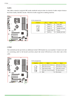
nForce 750i SLI Motherboard Power Connections 24-pin ATX Power PWR1 is the main power supply connector located along the edge of the board next to the DIMM slots. Make sure that the power supply cable and pins are properly aligned with the connector on the motherboard. Firmly plug the power supply cable into the connector and make sure it is secure. v Pin Assignments Connector Pin Signal 1 +3.3V 2 +3.3V 3 GND 4 +5V 5 GND 6 +5V 7 GND 8 PWROK 9 +5V_AUX 10 +12V 11 +12V 12 +3.3V Pin Signal 13 +3.3V 14 -12V 15 GND 16 PS_ON 17 GND 18 GND 19 GND 20 RSVD 21 +5V 22 +5V 23 +5V 24 GND 8-pin ATX 12V Power The 8-pin ATX 12V power connection, is used to provide power to the CPU. Align the pins to the connector and press firmly until seated. v Pin Assignments Connector Pin Signal 1 GND 2 GND 3 GND 4 GND Pin Signal 5 +12V 6 +12V 7 +12V 8 +12V 11
-
 1
1 -
2
-
3
-
4
-
5
-
6
-
7
-
8
-
9
-
10
-
11
-
12
-
13
-
 14
14 -
 15
15 -
 16
16 -
 17
17 -
 18
18 -
 19
19 -
 20
20 -
 21
21 -
 22
22 -
 23
23 -
 24
24 -
25
-
26
-
27
-
28
-
29
-
30
-
31
-
32
-
33
-
34
-
35
-
36
-
37
-
38
-
39
-
40
-
41
-
42
-
43
-
44
-
45
-
46
-
47
-
48
-
49
-
50
-
51
-
52
-
53
-
54
-
55
-
56
-
57
-
58
 |
 |
