EVGA 123-YW-E175-A1 User Manual - Page 23
IEEE 1394a, USB Headers - sli nforce motherboard
 |
UPC - 843368004507
View all EVGA 123-YW-E175-A1 manuals
Add to My Manuals
Save this manual to your list of manuals |
Page 23 highlights
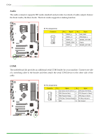
nForce 750i SLI Motherboard IEEE 1394a The IEEE 1394 expansion cable bracket is provided in the box but if you do not require the additional external connections, you do not need to install it. 1. Secure the bracket to either the front or rear panel of your chassis (not all chassis are equipped with the front panel option). 2. Connect the two ends of the cables to the IEEE 1394 connectors on the motherboard. v Pin Assignments Connector Pin Signal 1 TPA+ 3 GND 5 TPB+ 7 +12V 9 Empty Pin Signal 2 TPA4 GND 6 TPB8 +12V 10 GND USB Headers This motherboard contains six (6) USB 2.0 ports that are exposed on the rear panel of the chassis (Figure 2). The motherboard also contains one 10-pin internal header connectors onboard that can be used to connect an optional external bracket containing four (2) more USB 2.0 ports. 1. Secure the bracket to either the front or rear panel of your chassis (not all chassis are equipped with the front panel option). 2. Connect the two ends of the cables to the USB 2.0 headers on the motherboard. v Pin Assignments Connector Pin Signal 1 5V_DUAL 3 Data5 Data+ 7 GND 9 Empty Pin Signal 2 5V_DUAL 4 Data6 Data+ 8 GND 10 No Connect
-
 1
1 -
2
-
3
-
4
-
5
-
6
-
7
-
8
-
9
-
10
-
11
-
12
-
13
-
14
-
15
-
16
-
17
-
 18
18 -
 19
19 -
 20
20 -
 21
21 -
 22
22 -
 23
23 -
 24
24 -
 25
25 -
 26
26 -
 27
27 -
 28
28 -
29
-
30
-
31
-
32
-
33
-
34
-
35
-
36
-
37
-
38
-
39
-
40
-
41
-
42
-
43
-
44
-
45
-
46
-
47
-
48
-
49
-
50
-
51
-
52
-
53
-
54
-
55
-
56
-
57
-
58
 |
 |
