EVGA 132-CK-NF78-TR User Manual - Page 18
EVGA nForce 780i SLI Motherboard Layout, Chassis Backpanel Connectors - nforce 780i sli ()
 |
View all EVGA 132-CK-NF78-TR manuals
Add to My Manuals
Save this manual to your list of manuals |
Page 18 highlights
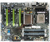
nForce 780i SLI Motherboard 10. Serial-ATA (SATA) connectors 20. FP Audio connector Figure 1. EVGA nForce 780i SLI Motherboard Layout 7 7 1 2 3 4 5 6 4 4 1. PS/2 Mouse Port 2. PS/2 Keyboard Port 3. 1394a (Firewire) Port 4. USB 2.0 ports (SIX) 5. SPDIF output 6. Port Blue Green Pink Orange Black Grey 2-Channel Line-In Line-Out Mic In 4-Channel Line-In Front Speaker Out Mic In Rear Speaker Out 6-Channel/8-Channel Line-In Front Speaker Out Mic In Center/Subwoofer Rear Speaker Out 7. Lan Port with LEDs to indicate status. • Yellow/Light Up/Blink = 10 Mbps/Link/Activity • Yellow and Green/Light Up/Blink = 100 Mbps/link/Activity • Green/Light Up/Blink = 1000 Mbps/Link/Activity Figure 2. Chassis Backpanel Connectors
-
 1
1 -
2
-
3
-
4
-
5
-
6
-
7
-
8
-
9
-
10
-
11
-
12
-
 13
13 -
 14
14 -
 15
15 -
 16
16 -
 17
17 -
 18
18 -
 19
19 -
 20
20 -
 21
21 -
 22
22 -
 23
23 -
24
-
25
-
26
-
27
-
28
-
29
-
30
-
31
-
32
-
33
-
34
-
35
-
36
-
37
-
38
-
39
-
40
-
41
-
42
-
43
-
44
-
45
-
46
-
47
-
48
-
49
-
50
-
51
-
52
-
53
-
54
-
55
-
56
-
57
-
58
-
59
-
60
-
61
-
62
-
63
-
64
-
65
-
66
-
67
-
68
-
69
-
70
-
71
-
72
-
73
-
74
-
75
-
76
-
77
-
78
-
79
-
80
-
81
-
82
-
83
-
84
-
85
-
86
-
87
-
88
-
89
-
90
-
91
-
92
-
93
-
94
-
95
-
96
-
97
-
98
-
99
-
100
-
101
-
102
-
103
-
104
-
105
-
106
-
107
-
108
-
109
-
110
-
111
-
112
-
113
-
114
-
115
-
116
-
117
-
118
-
119
-
120
-
121
-
122
-
123
-
124
-
125
-
126
-
127
 |
 |

nForce 780i SLI Motherboard
10. Serial-ATA (SATA) connectors
20. FP Audio connector
Figure 1.
EVGA nForce 780i SLI Motherboard Layout
1. PS/2 Mouse Port
2. PS/2 Keyboard Port
3. 1394a (Firewire) Port
4. USB 2.0 ports (SIX)
5. SPDIF output
6. Port
2-Channel
4-Channel
6-Channel/8-Channel
Blue
Line-In
Line-In
Line-In
Green
Line-Out
Front Speaker Out
Front Speaker Out
Pink
Mic In
Mic In
Mic In
Orange
Center/Subwoofer
Black
Rear Speaker Out
Rear Speaker Out
Grey
7. Lan Port with LEDs to indicate status.
•
Yellow/Light Up/Blink = 10 Mbps/Link/Activity
•
Yellow and Green/Light Up/Blink = 100 Mbps/link/Activity
•
Green/Light Up/Blink = 1000 Mbps/Link/Activity
Figure 2.
Chassis Backpanel Connectors
1
2
5
6
7
4
3
4
7
4