EVGA 132-YW-E178-A1 User Guide
EVGA 132-YW-E178-A1 Manual
 |
View all EVGA 132-YW-E178-A1 manuals
Add to My Manuals
Save this manual to your list of manuals |
EVGA 132-YW-E178-A1 manual content summary:
- EVGA 132-YW-E178-A1 | User Guide - Page 1
User Guide EVGA force 780i SLI FTW Motherboard - EVGA 132-YW-E178-A1 | User Guide - Page 2
EVGA ii - EVGA 132-YW-E178-A1 | User Guide - Page 3
of the Kit...ix EVGA nForce 780i SLI FTW Motherboard 1 Motherboard Specifications ...1 Unpacking and Parts Descriptions ...3 Unpacking ...3 Equipment ...3 EVGA nForce 780i SLI FTW Motherboard 4 Hardware Installation ...7 Safety Instructions...7 Preparing the Motherboard...8 Installing the CPU - EVGA 132-YW-E178-A1 | User Guide - Page 4
...22 PCI Express x1 Slot ...23 PCI Express x16 Slots...23 Clear CMOS Button ...24 Configuring the BIOS ...25 Enter BIOS Setup ...26 Main Menu ...26 Standard CMOS Features Menu 28 Date and Time ...29 IDE Channel and For OS 36 Full Screen LOGO Show ...36 Advanced Chipset Features ...37 EVGA iv - EVGA 132-YW-E178-A1 | User Guide - Page 5
System BIOS Cacheable ...37 HPET Function ...37 Integrated Peripherals Menu ...38 IDE Function Setup...39 RAID Config...40 USB Config ...40 MAC Config ...45 Reset Configuration Data...45 Resources Controlled By ...46 IRQ Resources ...46 PCI/VGA Palette Snoop ...46 Maximum Payload Size ...47 EVGA v - EVGA 132-YW-E178-A1 | User Guide - Page 6
...51 HT Multiplier ...51 Spread Spectrum ...52 FSB & Memory Config ...53 SLI Ready Memory ...53 FSB & Memory clock mode ...54 FSB (QDR), MHz ...55 Optimal ...55 Expert ...56 CPU Feature ...57 Limit CPUID MaxVal...57 Intel SpedStep ...57 PPM Mode ...57 CPU Thermal Control ...58 C1E Enhanced Halt - EVGA 132-YW-E178-A1 | User Guide - Page 7
Lane 0-2 ...60 GTLVREF Lane 3 ...60 NVMEM Memory Test ...60 Load Timing/Voltage Set ...61 Save Timing/Voltage Set ...61 Installing Drivers and Software ...63 Driver Installation...63 EVGA Enthusiast Glossary...65 Appendix A. POST Codes for EVGA nForce 780i SLI FTW Platform 67 NVMM POST Codes ...73 - EVGA 132-YW-E178-A1 | User Guide - Page 8
9. Figure 10. Figure 11. Figure 12. Figure 13. Figure 14. Figure 15. Figure 16. EVGA nForce 780i SLI FTW Motherboard Layout 5 Chassis Back Panel Connectors 6 Power Supply Connectors 12 PWR1 Motherboard Connector 13 BIOS CMOS Setup Utility Main Menu 27 Standard CMOS Features Menu 29 Advanced - EVGA 132-YW-E178-A1 | User Guide - Page 9
the hardware necessary to install and connect your new EVGA force® 780i SLI FTW motherboard. However, it does not contain the following items that must be purchased separately to make the motherboard functional. Intel microprocessor System Memory Cooling fan for the microprocessor Graphics - EVGA 132-YW-E178-A1 | User Guide - Page 10
- EVGA 132-YW-E178-A1 | User Guide - Page 11
EVGA nForce 780i SLI FTW Motherboard Thank you for buying the EVGA nFore 780i SLI FTW Motherboard: This motherboard offers the tools and performance PC users' demand. When combined with two or three SLIReady NVIDIA GeForce graphics cards, you get innovative NVIDIA SLI Technology for enhanced system - EVGA 132-YW-E178-A1 | User Guide - Page 12
Supports 8-channel audio Supports S/PDIF output Supports Jack-Sensing function Triple PCI Express x16 Support 2 x16 PCI Express 2.0 1 x16 PCI Express 1.0 Supports features Green Function Supports ACPI (Advanced Configuration and Power Interface) Supports S0 (normal), S1 (power - EVGA 132-YW-E178-A1 | User Guide - Page 13
following equipment is included in the EVGA nForce 780i SLI FTW motherboard box. (Accessories may vary between models, see product package) EVGA nForce 780i SLI FTW Motherboard This PCI Express motherboard contains the NVIDIA nForce 780i SLI SPP and MCP and is SLI-ready. I/O Shield Installs in the - EVGA 132-YW-E178-A1 | User Guide - Page 14
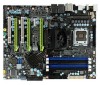
the IDE connection on both the Motherboard and IDE device EVGA nForce 780i SLI FTW Motherboard The EVGA nForce 780i SLI FTW motherboard with the NVIDIA nForce 780i SLI SPP and MCP processor is a PCI Express, SLI-ready motherboard. Figure 1 shows the motherboard and Figures 2 shows the back panel - EVGA 132-YW-E178-A1 | User Guide - Page 15
28 20 29 19 10 18 17 13 1 13 16 2 3 15 4 30 14 13 11 12 7 9 8 7 6 5 13 Figure 1. EVGA nForce 780i SLI FTW Motherboard Layout 1. CPU Socket - For use with Intel LGA 775 CPUs 2. NVIDIA SPP with Active fan - Also known as the Northbridge 3. CPU fan connector - Connect CPU Fan to this - EVGA 132-YW-E178-A1 | User Guide - Page 16
Mbps/link/Activity Green/Light Up/Blink = 1000 Mbps/Link/Activity 6-Channel/8-Channel Line-In Front Speaker Out Mic In Center/Subwoofer Rear Speaker Out EVGA 6 - EVGA 132-YW-E178-A1 | User Guide - Page 17
section will guide you through the installation of the motherboard. The topics covered in this section are: Preparing the motherboard Installing the CPU Installing the CPU fan Installing the memory Installing the motherboard Connecting cables and setting switches Safety Instructions To - EVGA 132-YW-E178-A1 | User Guide - Page 18
of the processor. Use the following procedure to install the CPU onto the motherboard. 1. Unhook the socket lever by pushing down and away from the socket. are many different fan types that can be used with this motherboard. Follow the instructions that came with your fan assembly. Be sure that the - EVGA 132-YW-E178-A1 | User Guide - Page 19
System Memory (DIMMs) Your new motherboard has four 1.8V 240-pin slots for DDR2 memory. These slots support 256 MB, 512 MB, 1 GB, and 2 GB DDR2 memory modules. They also support dual channel DDR2 memory technology up to of the DIMM slot automatically lock the DIMM into the connector. EVGA 9 - EVGA 132-YW-E178-A1 | User Guide - Page 20
motherboard The motherboard kit motherboard supplier. Securing the Motherboard into the Chassis on the motherboard, it is recommended motherboard using a minimum of eight (8) to ten (10) spacers. 1. Carefully place the motherboard instruction. 5. Secure the motherboard with a minimum of eight-to-ten screws - EVGA 132-YW-E178-A1 | User Guide - Page 21
you through all the connections and switch settings necessary on the motherboard. This will include: Power Connections 24-pin ATX power (PWR1) 8-pin ATX 12V power (PWR2) Internal Headers Front panel page 5 to locate the connectors and jumpers referenced in the following procedure. EVGA 11 - EVGA 132-YW-E178-A1 | User Guide - Page 22
Power Connections To support 3-way SLI, this motherboard has the following specific minimum power supply requirements: A Power Supply that features 1000 W peak power 6-pin and/ requirements are for your specific configuration or a certified power supply vendor, refer to www.slizone.com. EVGA 12 - EVGA 132-YW-E178-A1 | User Guide - Page 23
-pin ATX Power (PWR1) PWR1 is the main power supply connector located along the edge of the board next to the DIMM slots. Make sure that the power supply cable and pins are properly aligned with the connector on the motherboard. Firmly 17 GND 18 GND 19 GND 20 RSVD 21 +5V 22 +5V 23 +5V 24 GND EVGA 13 - EVGA 132-YW-E178-A1 | User Guide - Page 24
force in. 5 12V 8 1 GND 4 Connecting IDE Hard Disk Drives The IDE connector supports Ultra ATA 133/100/66 IDE hard disk drives. 1. Connect the blue connector (the cable end with a single connector) to the motherboard. 2. Connect the black connector (the cable with the two closely spaced black and - EVGA 132-YW-E178-A1 | User Guide - Page 25
to connect the Serial ATA II device to the motherboard. These connectors support the thin Serial ATA II cables for primary storage to 300MB/s data transfer rate. There are six serial ATA connectors on the motherboard that support RAID 0, RAID 1, RAID 5, RAID 0+1 and JBOD configurations. SATA 3 - EVGA 132-YW-E178-A1 | User Guide - Page 26
Connecting Internal Headers Front Panel Header The front panel header on this motherboard is one connector used to connect the following four cables: (see Table 2 for pin definitions) PWRLED Attach panel of the case to these two pins. The system restarts when the RESET switch is pressed. EVGA 16 - EVGA 132-YW-E178-A1 | User Guide - Page 27
equipped with the front panel option). 2. Connect the two ends of the cables to the IEEE 1394a connectors on the motherboard. Table 3. IEEE 1394a Connector Pins Connector IEEE 1394a Connector 10 9 8 7 6 5 4 3 2 1 Pin Signal 1 TPA+ 2 TPA- 3 GND 4 GND 5 TPB+ 6 TPB- 7 +12V - EVGA 132-YW-E178-A1 | User Guide - Page 28
the rear panel of the chassis (Figure 2). The motherboard also contains two 10-pin internal header connectors onboard that option). 2. Connect the two ends of the cables to the USB 2.0 headers on the motherboard. Table 4. USB 2.0 Header Pins Connector Pin USB 2.0 Header Connector 1 3 10 9 - EVGA 132-YW-E178-A1 | User Guide - Page 29
HD audio standard and provides two kinds of audio output choices: Front Audio and Rear Audio. The front Audio supports re-tasking function. Table 5. Front Audio Connector Connector Front Audio Connector 1 2 3 4 5 6 7 8 9 10 Pin Signal 1 PORT1_L 2 AUD_GND 3 PORT1_R 4 PRECENCE_J - EVGA 132-YW-E178-A1 | User Guide - Page 30
or a 4-pin connector. Connect a 3-pin connector to pins 1, 2, and 3 on the motherboard connector. CPU Fan Connector 4 3 2 GN1D SENSE PWR CONTROL EVGA 20 EVGA nForce 780i SLI SPP/MCP fan connector Install the fan over the nForce 780i SLI SPP to draw heat from the MCP. The fan plugs into a 3-pin - EVGA 132-YW-E178-A1 | User Guide - Page 31
There are four more optional fan connectors on the motherboard that can be used for adding more system fans. 1 GND +12V SENSE System fan connector Fan Connector 3 2 1 GND +12V SENSE The motherboard kit provides an additional serial COM header for your machine. Connect one side of a switching cable - EVGA 132-YW-E178-A1 | User Guide - Page 32
Floppy Disk Drive (FDD) Connector The motherboard supports a standard 360K, 720K, 1.2M, 1.44m, and a 2.88M floppy disk drive (FDD). Expansion Slots The EVGA nForce 780i SLI FTW motherboard contains six expansion slots, four PCI Express slots and two PCI slots. 1 2 1 2 3 2 1 - PCI slots 2 - - EVGA 132-YW-E178-A1 | User Guide - Page 33
x16 slots are reserved for graphics or video cards. The design of this motherboard supports three PCI-Express graphics cards using NVIDIA's SLI technology. When installing a PCI Express x16 card, be sure the retention clip the chassis back panel with the screw used to hold the blank cover. EVGA 23 - EVGA 132-YW-E178-A1 | User Guide - Page 34
motherboard contains a button to clear BIOS configurations back to default settings. Please see Figure 1 on page 6 for location. Clear CMOS Button The motherboard Clear CMOS Button Onboard System Reset and Power Buttons The motherboard provides an onboard Power and Reset button. The Yellow Reset - EVGA 132-YW-E178-A1 | User Guide - Page 35
are also provided. This section includes the following information: Enter BIOS Setup Main Menu Standard CMOS Features Advanced BIOS Features Advanced Chipset Features Integrated Peripherals Power Management Setup PnP/PCI Configurations PC Health Status Frequency/Voltage - EVGA 132-YW-E178-A1 | User Guide - Page 36
following procedure to verify/change BIOS settings. 1. Power on Phoenix-Award BIOS CMOS Setup Utility. It is strongly recommended that you do not change the default BIOS settings. Changing to the previous menu, press Esc. Note that on the BIOS screens all data in white is for information only, data - EVGA 132-YW-E178-A1 | User Guide - Page 37
: Quit F10 : Save & Exit Setup Select Item Time, Date, Hard Disk Type.., SLI-Ready memory - Disabled Figure 5. BIOS CMOS Setup Utility Main Menu Standard CMOS Features Use this menu to set up the to optimize system performance and configure clocks, voltages, memory timings, and more. EVGA 27 - EVGA 132-YW-E178-A1 | User Guide - Page 38
the bottom of the BIOS screen. The three status indicators are: Enabled: SLI-Ready memory is detected and enabled. Disabled: SLI-Ready memory is detected but disabled. Not Detected: SLI-Ready memory is not detected in the option you choose. To go back to the previous menu, press Esc. EVGA 28 - EVGA 132-YW-E178-A1 | User Guide - Page 39
:mm:ss) Sat, Jul 01 2006 12 : 48: 23 Item Help IDE Channel 0 Master IDE Channel 0 Slave SATA 1 (A0) SATA 2 (A1) SATA 3 (B0) SATA 4 (B1) SATA 5 (C0) SATA 6 (C1) Drive A Halt On Base Memory Extended Memory Total Memory [None yy) Time (hh:mm:ss) Sat, Jul 01 2006 14 : 48: 43 EVGA 29 - EVGA 132-YW-E178-A1 | User Guide - Page 40
/SATA sub-menu. IDE Channel 0 Master IDE Channel 0 Slave SATA 1 (A0) SATA 2 (A1) SATA 3 (B0) SATA 4 (B1) SATA 5 (C0) SATA 6 (C1) [None] can auto-detect the hard disk when booting up. Manual When you set the channel to [Manual] and change Access Mode to [CHS], you can then enter - EVGA 132-YW-E178-A1 | User Guide - Page 41
Capacity Cylinder Head Precomp Landing Zone Sector [Press Enter] [Manual} [CHS] 0 MB .....0 [ 0] [ 0] [ 0] [ 0] Press ENTER to display sub-menu or Cylinder The BIOS supports the following HDD Access Modes: Min= 0 Max=65535 Key to the Standard CMOS Features menu. ENTER:Accept ESC:Abort EVGA 31 - EVGA 132-YW-E178-A1 | User Guide - Page 42
Keyboard] Press ENTER to display sub-menu All Errors Whenever the BIOS detects a nonfatal error; the system stops and prompts you. No by the BIOS POST (Power-On Self Test). Base Memory BIOS POST determines in the system. Extended Memory BIOS determines how much extended memory is - EVGA 132-YW-E178-A1 | User Guide - Page 43
Advanced BIOS display the sub-menus. Phoenix - AwardBIOS CMOS Setup Utility Advanced BIOS Features Removable Device Priority Hard Disk Boot Priority F1:General Help F5: Previous Values F7:Defaults Figure 7. Advanced BIOS Features Menu Note that all data in white is for information only - EVGA 132-YW-E178-A1 | User Guide - Page 44
while booting, which reduces the time needed to boot the system. Use the Page Up and Page Down keys to toggle between Enable and Disable. EVGA 34 - EVGA 132-YW-E178-A1 | User Guide - Page 45
to enable or disable the Advanced Programmable Interrupt Controller (APIC). If you disable this option, you also disable the MPS Version Control for OS option. EVGA 35 - EVGA 132-YW-E178-A1 | User Guide - Page 46
MPS Version Control For OS Use this function to select the Multi-Processor Specification (MPS) version that BIOS passes to the operating system. Use the Page Up and Page Down keys to scroll through the the system boots. Use the Page Up and Page Down keys to toggle between Enable and Disable EVGA 36 - EVGA 132-YW-E178-A1 | User Guide - Page 47
enable or disable caching the system BIOS. HPET Function This function allows you to enable or disable the High Precision Even Timer (HPET). When Enabled, HPET is used as the timing hardware for multimedia and other time-sensitive application. When HPET is Disabled, the APIC timer is used. EVGA 37 - EVGA 132-YW-E178-A1 | User Guide - Page 48
Help Main Level Move Enter:Select +/-/PU/PD:Value F10:Save ESC:Exit F1:General Help F5: Previous Values F7:Defaults Figure 9. Integrated Peripherals Menu EVGA 38 - EVGA 132-YW-E178-A1 | User Guide - Page 49
controllers. The options available are [SATA-0], [SATA-0+1], [Enable All], and [Disabled]. IDE Prefetch Mode Use this function to enable or disable the IDE Prefetch mode. EVGA 39 - EVGA 132-YW-E178-A1 | User Guide - Page 50
and cannot be changed. Versions that can be selected are [V1.1+V2.0] or [V1.1]. USB Keyboard/Mouse Support Use these function to enable or disable the onchip WSB support of the keyboard and/or mouse. OnChip USB x USB Keyboard Support x USB Mouse Support [Disabled] Enabled Enabled EVGA 40 - EVGA 132-YW-E178-A1 | User Guide - Page 51
detect the optimal number of block read/writes per sector the drive can support. Select [Disabled] if your drive does not support block mode. Onboard FDC Controller This function on the Integrated Peripherals menu . Options are [3F8/IRQ4], 2E8/IRQ3], [3E8/IRQ4], [Auto], and [Disabled]. EVGA 41 - EVGA 132-YW-E178-A1 | User Guide - Page 52
the Power Management Setup menu allows you to select an ACPI Suspend Type. Types to select from are [S1&S3], [S1(POS)], and [S3(STR)]. EVGA 42 - EVGA 132-YW-E178-A1 | User Guide - Page 53
on by alarm function. Set to [Disable] to prevent power-on by alarm. When set to [Enable], you can manually put in the day of the month and the time of the alarm. Power-on by Alarm Day of Month Alarm scroll through numbers or enter the number using the keyboard number or the + and - keys. EVGA 43 - EVGA 132-YW-E178-A1 | User Guide - Page 54
though Ctrl+F12 POWER ON Function x KB Power ON Password Hot Key Power On [Hot key] Enter [Ctrl-F1] Mouse Left Mouse Right Any Key EVGA 44 - EVGA 132-YW-E178-A1 | User Guide - Page 55
function on the PnP/PCI Configuration menu allows you to enable or disable the resetting of Extended System Configuration Data (ESCD) when you exit Setup. EVGA 45 - EVGA 132-YW-E178-A1 | User Guide - Page 56
, and memory base address fields. Select [Auto(ESCD)] if you want the BIOS to automatically populate these fields. If you select [Manual] so you can assign the resources, IRQ Resources is enabled for input. Resources menu allows you to enable or disable the Palette Snoop function. EVGA 46 - EVGA 132-YW-E178-A1 | User Guide - Page 57
Board MCP CPU Core CPU FSB Memory +3.3V +3.3V Dual +12V +5V +Vbat CPU Fan Speed Aux Fan Speed nForce Fan Speed Chassis Fan Speed Chassis Fan2 Speed Phoenix - AwardBIOS CMOS Setup Utility System Monitor [Press Enter] 42ºC/ 108ºF voltages of the various components change with system usage. EVGA 47 - EVGA 132-YW-E178-A1 | User Guide - Page 58
control the speed of the various fans on the motherboard. Set CPU fan speed, Chassis Fan, and nForce Fan to [SmartFan] when you want the speed of the fans automatically controlled based on temperature. To set the fan speed to a constant rate, select [Manual] and then enter the speed from 0% to 100 - EVGA 132-YW-E178-A1 | User Guide - Page 59
- EVGA 132-YW-E178-A1 | User Guide - Page 60
Help F5: Previous Values F7:Defaults Dummy O.C Choose different levels of CPU OC 5%, 10%, 15%, 20%, and 25% increments. This function will allow to automatically overclock your CPU. The O.C's stability will rely on the CPU type, good CPU's heat dissipation, O.C memory modules and so on - EVGA 132-YW-E178-A1 | User Guide - Page 61
in Figure 9, all of the options are listed. On the actual BIOS screen, you will need to scroll down to see all the options. = FSB Ref Clock/4 * CPU Multiplier **HT Multiplier** nForce SPP --> nForce MCP nForce SPP - EVGA 132-YW-E178-A1 | User Guide - Page 62
clock between the SPP chip and the MCP chip. HT Multiplier nForce SPP - -> nForce MCP Use the Page Up and Page Down keys to scroll through SPP chip to the MCP chip. Values are [1 x] through [5 x]. nForce MCP - EVGA 132-YW-E178-A1 | User Guide - Page 63
for the CPU. Option values are [Disabled], [UP Spread], and [Center Spread]. HT Spread Spectrum Disabled PCIe Spread Spectrum(MCP) Disabled SATA Spread Spectrum Disabled EVGA 52 - EVGA 132-YW-E178-A1 | User Guide - Page 64
Item Help Main Level "CPUOC MAX" realizes the complete optimized memory settings when SLI-Ready memory is installed Optimized memory settings by allowing X% CPU overclocking CPU overclocking may require manual overvolting of the CPU to improve system stability Move Enter:Select +/-/PU/PD:Value - EVGA 132-YW-E178-A1 | User Guide - Page 65
to Unlinked and cannot be changed until SLI-Ready Memory is set to Disable. Please note when enabling SLI -Ready memory, timings and voltages will QDR), MHz is changed to editable and the FSB speed can be entered manually. As the FSB speed is changed, CPU Freq, MHz changes proportionally. CPU EVGA 54 - EVGA 132-YW-E178-A1 | User Guide - Page 66
timings or to manually enter timings. Phoenix Help Main Level Select [Expert] to enter timings manually Move Enter:Select +/-/PU/PD:Value F10:Save ESC:Exit Optimal. Optimal prohibits you from manually setting any timing. All timing manual input. Note that you should set the - EVGA 132-YW-E178-A1 | User Guide - Page 67
-to-read delay with the same chip selected (options are 1 through 10). tREF: This is the DRAM refresh rate (options are Auto, 7.8uS, and 3.9uS). EVGA 56 - EVGA 132-YW-E178-A1 | User Guide - Page 68
Phoenix - AwardBIOS CMOS Setup Utility CPU Feature Limit CPUID MaxVal Intel SpeedStep x PPM Mode CPU Thermal Control C1E Enhanced Halt State limit of the CPUID MaxVal to 3. Set to Disable for Win XP. Intel SpeedStep If enabled, CPU clock speed and CPU core voltage are adjusted dynamically based - EVGA 132-YW-E178-A1 | User Guide - Page 69
TM1 and TM2 support. Options are: Disable Disable support for TM1 CPU core voltage. TM1 & TM2 Enables support for both TM1 and TM2. C1E when the operating system issues a halt instruction. Execute Disable Bit When this provided by Intel Virtualization Technology. CPU Core 1-3 - EVGA 132-YW-E178-A1 | User Guide - Page 70
the voltage level for the DRAM. Use the Page Up and Page Down keys to select a voltage or select [Auto] to automatically set the voltage. nForce SPP This function defines the core voltage level for the NVIDIA nForce SPP chip. Use the EVGA 59 - EVGA 132-YW-E178-A1 | User Guide - Page 71
voltage. nForce MCP This function defines the core voltage level for the NVIDIA nForce MCP chip. HT nForce SPP MCP This function defines the voltage level for the NVIDIA HT nForce SPP nForce MCP Auxiliary This function defines the core voltage level for the NVIDIA nForce MCP Auxiliary - EVGA 132-YW-E178-A1 | User Guide - Page 72
. Press Enter to see the options. Save timing/voltage set Press Enter to Exit Select Profile 1 Select Profile 2 Select Profile 3 :Move ENTER:Accept ESC:Abort EVGA 61 - EVGA 132-YW-E178-A1 | User Guide - Page 73
EVGA 62 - EVGA 132-YW-E178-A1 | User Guide - Page 74
shipped with your EVGA motherboard contains the following software and drivers: NVIDIA nForce motherboard drivers Audio drivers RAID drivers Adobe Acrobat Reader User's Manual Driver Installation 3. Insert the EVGA nForce 780i SLI FTW installation CD for the motherboard included in the - EVGA 132-YW-E178-A1 | User Guide - Page 75
EVGA 64 - EVGA 132-YW-E178-A1 | User Guide - Page 76
EVGA Glossary of Terms: ACPI - Advanced Configuration and Power Interface AFR - Alternate Frame Rendering APIC - Advanced Programmable Interrupt Controller BIOS Digital Video Interface FDC - Floppy Disk Controller FSB - Front Side Bus FTW - For The Win! GHz - Gigahertz GPU - Graphics Processing Unit - EVGA 132-YW-E178-A1 | User Guide - Page 77
LCD - Liquid Crystal Display LGA - Land Grid Array LN2 - Liquid Nitrogen Cooling MAC - Media Access Control Attachment SB - Southbridge SCSI - Small Computer System Interface SFR - Split Frame Rendering SLI - Scalable Link Interface SPD - Serial Presence Detect SPDIF - Sony/Philips Digital - EVGA 132-YW-E178-A1 | User Guide - Page 78
Appendix A. POST Codes for the EVGA nForce 780i SLI FTW Motherboard This section provides the Award POST Codes (Table 6) and the NVMM POST Codes (Table 7) for EVGA nForce 780i SLI FTW Motherboard during system boot up. These POST Codes are displayed on the LED POST Code readout located directly - EVGA 132-YW-E178-A1 | User Guide - Page 79
EVGA 68 Award POST Codes Code 0E 0F 10 11 12 Name CheckSum Check Reserved 2A Reserved 2B Init video 2C Reserved 2D Video memory test Description Check the integrity of the ROM,BIOS and message Check Flash type and copy flash write/erase routines Test and Reset CMOS Load Chipset Defaults - EVGA 132-YW-E178-A1 | User Guide - Page 80
checksum is good, execute EISA initialization. If not, execute ISA tests and clear EISA mode flag. Size base memory from 256K to 640K and extended EVGA 69 - EVGA 132-YW-E178-A1 | User Guide - Page 81
EVGA 70 Award POST Codes Code Name 4A Reserved 4B Reserved 4C Reserved 4D Reserved 4E Init APIC 4F Reserved 50 USB init 51 Reserved 52 - EVGA 132-YW-E178-A1 | User Guide - Page 82
check and auto configuration check up Initialize floppy disk drive Install FDD and setup BIOS data area parameters Initialize hard drive controller IDE device detection Initialize serial ports. Initialize RAM and clear screen. Display PNP devices Final USB initialization Setup ACPI tables EVGA 71 - EVGA 132-YW-E178-A1 | User Guide - Page 83
protected mode. If unmasked NMI occurs, display Press F1 to disable NMI, F2 reboot. To program chipset from defaults values E1- Page 1, E2 - Page 2, etc. EVGA 72 - EVGA 132-YW-E178-A1 | User Guide - Page 84
geometry (using SPD) Prepare MRS variables Probe memory geometry PROD_C: PROD f/ Calculated ref manuals PROD_D: PROD w/ Discrete assembly programming PROD_E: PROD w/ Expandable criteria Send MRS/EMRS Power State SLAM table Hardware Workarounds Restore, and exit NVMM Memory Test EVGA 73 - EVGA 132-YW-E178-A1 | User Guide - Page 85
0F8h 0F7h 0F6h 0F5h 0F4h Description ERROR handler End of Table Invalid APIC ID CPU Identify/Init failed North Bridge not supported South Bridge not supported No DIMMs present Invalid DIMM types, SDR/DDR Different voltage levels Invalid REFRESH Rate Invalid memory geometry Slam Engine error Memory
-
 1
1 -
 2
2 -
 3
3 -
 4
4 -
 5
5 -
 6
6 -
 7
7 -
8
-
9
-
10
-
11
-
12
-
13
-
14
-
15
-
16
-
17
-
18
-
19
-
20
-
21
-
22
-
23
-
24
-
25
-
26
-
27
-
28
-
29
-
30
-
31
-
32
-
33
-
34
-
35
-
36
-
37
-
38
-
39
-
40
-
41
-
42
-
43
-
44
-
45
-
46
-
47
-
48
-
49
-
50
-
51
-
52
-
53
-
54
-
55
-
56
-
57
-
58
-
59
-
60
-
61
-
62
-
63
-
64
-
65
-
66
-
67
-
68
-
69
-
70
-
71
-
72
-
73
-
74
-
75
-
76
-
77
-
78
-
79
-
80
-
81
-
82
-
83
-
84
-
85
 |
 |

User Guide
EVGA force 780i SLI FTW
Motherboard