EVGA 132-YW-E178-A1 User Guide - Page 16
Chassis Back Panel Connectors
 |
View all EVGA 132-YW-E178-A1 manuals
Add to My Manuals
Save this manual to your list of manuals |
Page 16 highlights
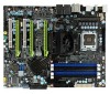
7 7 1 2 3 4 5 6 4 4 Figure 2. Chassis Back Panel Connectors 1. PS/2 Mouse Port 2. PS/2 Keyboard Port 3. 1394a (Firewire) Port 4. USB 2.0 ports (SIX) 5. SPDIF output 6. Port Blue Green Pink Orange Black Grey 2-Channel Line-In Line-Out Mic In 4-Channel Line-In Front Speaker Out Mic In Rear Speaker Out 7. LAN Port with LEDs to indicate status. Yellow/Light Up/Blink = 10 Mbps/Link/Activity Yellow and Green/Light Up/Blink = 100 Mbps/link/Activity Green/Light Up/Blink = 1000 Mbps/Link/Activity 6-Channel/8-Channel Line-In Front Speaker Out Mic In Center/Subwoofer Rear Speaker Out EVGA 6
-
 1
1 -
2
-
3
-
4
-
5
-
6
-
7
-
8
-
9
-
10
-
 11
11 -
 12
12 -
 13
13 -
 14
14 -
 15
15 -
 16
16 -
 17
17 -
 18
18 -
 19
19 -
 20
20 -
 21
21 -
22
-
23
-
24
-
25
-
26
-
27
-
28
-
29
-
30
-
31
-
32
-
33
-
34
-
35
-
36
-
37
-
38
-
39
-
40
-
41
-
42
-
43
-
44
-
45
-
46
-
47
-
48
-
49
-
50
-
51
-
52
-
53
-
54
-
55
-
56
-
57
-
58
-
59
-
60
-
61
-
62
-
63
-
64
-
65
-
66
-
67
-
68
-
69
-
70
-
71
-
72
-
73
-
74
-
75
-
76
-
77
-
78
-
79
-
80
-
81
-
82
-
83
-
84
-
85
 |
 |

EVGA
6
Figure 2.
Chassis Back Panel Connectors
1. PS/2 Mouse Port
2. PS/2 Keyboard Port
3. 1394a (Firewire) Port
4. USB 2.0 ports (SIX)
5. SPDIF output
6. Port
2-Channel
4-Channel
6-Channel/8-Channel
Blue
Line-In
Line-In
Line-In
Green
Line-Out
Front Speaker Out
Front Speaker Out
Pink
Mic In
Mic In
Mic In
Orange
Center/Subwoofer
Black
Rear Speaker Out
Rear Speaker Out
Grey
7. LAN Port with LEDs to indicate status.
Yellow/Light Up/Blink = 10 Mbps/Link/Activity
Yellow and Green/Light Up/Blink = 100 Mbps/link/Activity
Green/Light Up/Blink = 1000 Mbps/Link/Activity
1
2
5
6
4
3
4
7
4
7