Epson Stylus Pro User Manual - Page 76
Timing chart, Notes
 |
View all Epson Stylus Pro manuals
Add to My Manuals
Save this manual to your list of manuals |
Page 76 highlights
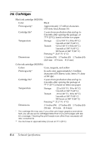
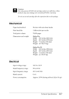
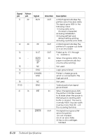
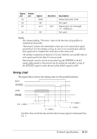
Signal pin 33 34 35 Return pin - Signal GND NC +5 V 36 - NC Direction - OUT - Description Same as for pins 19-30 Not used Pulled up to +5 V through 1 KΩ resistance Not used Notes: u The column heading "Direction" refers to the direction of signal flow as viewed from the printer. u "Return pin" denotes the twisted-pair return pin to be connected at signal ground level. For the interface wiring, be sure to use a twisted-pair cable for each signal and to complete the connection on the return side. u All interface conditions are based on TTL level. Both the rise and fall times of each signal must be less than 0.2 microseconds. u Data transfer must be carried out by observing the ACKNLG or BUSY signal. Data transfer to this printer can be carried out only after receipt of the ACKNLG signal or when the level of the BUSY signal is LOW. Timing chart The figure below shows the timing chart for the parallel interface. BUSY ACKNLG DATA STROBE 0.5 µs (Min.) 0 µs (Min.) 0 µs (Min.) 5 µs (Typ.) Transition time (both the rise and the fall) of every signal must be less than 0.2 µs. Technical Specifications B-11
-
 1
1 -
2
-
3
-
4
-
5
-
6
-
7
-
8
-
9
-
10
-
11
-
12
-
13
-
14
-
15
-
16
-
17
-
18
-
19
-
20
-
21
-
22
-
23
-
24
-
25
-
26
-
27
-
28
-
29
-
30
-
31
-
32
-
33
-
34
-
35
-
36
-
37
-
38
-
39
-
40
-
41
-
42
-
43
-
44
-
45
-
46
-
47
-
48
-
49
-
50
-
51
-
52
-
53
-
54
-
55
-
56
-
57
-
58
-
59
-
60
-
61
-
62
-
63
-
64
-
65
-
66
-
67
-
68
-
69
-
70
-
 71
71 -
 72
72 -
 73
73 -
 74
74 -
 75
75 -
 76
76 -
 77
77 -
 78
78 -
 79
79 -
 80
80 -
 81
81 -
82
-
83
-
84
-
85
-
86
-
87
-
88
-
89
-
90
-
91
-
92
-
93
-
94
-
95
-
96
-
97
-
98
 |
 |