Garmin GWX 70 Installation Manual - Page 11
GENERAL DESCRIPTION, 1.1 Introduction - specifications
 |
View all Garmin GWX 70 manuals
Add to My Manuals
Save this manual to your list of manuals |
Page 11 highlights
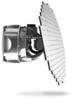
1 GENERAL DESCRIPTION 1.1 Introduction This manual is intended to provide mechanical and electrical information for use in the planning and design of an installation of the Garmin GWX 70 Weather Radar into an aircraft. This manual is not a substitute for an approved airframe-specific maintenance manual, installation design drawing, or complete installation data package. Attempting to install equipment by reference to this manual alone and without first planning or designing an installation specific to your aircraft may compromise your safety and is not recommended. The content of this manual assumes use by competent and qualified avionics engineering personnel and/or avionics installation specialists using standard aviation maintenance practices in accordance with Title 14 of the Code of Federal Regulations and other relevant accepted practices. This manual is not intended for use by individuals who do not possess the competencies and abilities set forth above. NOTE Garmin recommends installation of the GWX 70 by a Garmin-authorized installer. To the extent allowable by law, Garmin will not be liable for damages resulting from improper or negligent installation of the GWX 70. For questions, please contact Garmin Aviation Product Support at 1-888-606-5482. NOTE The ability of a weather radar system to accurately display weather returns is highly dependent upon the quality of the radome and its Transmission Efficiency. The specified performance of the GWX 70 Airborne Weather Radar can be achieved when installed behind a DO-213 Class A Radome within the RF window defined as +/-60 degrees from dead ahead in azimuth and +/-30 degrees from dead ahead in elevation. Refer to RTCA document DO-213 Class A for minimum operational performance standards for nose mounted radomes. 190-00829-01 Rev. C GWX 70 Installation Manual Page 1-1
-
 1
1 -
2
-
3
-
4
-
5
-
 6
6 -
 7
7 -
 8
8 -
 9
9 -
 10
10 -
 11
11 -
 12
12 -
 13
13 -
 14
14 -
 15
15 -
 16
16 -
17
-
18
-
19
-
20
-
21
-
22
-
23
-
24
-
25
-
26
-
27
-
28
-
29
-
30
-
31
-
32
-
33
-
34
-
35
-
36
-
37
-
38
-
39
-
40
-
41
-
42
-
43
-
44
-
45
-
46
-
47
-
48
-
49
-
50
-
51
-
52
-
53
-
54
-
55
-
56
-
57
-
58
-
59
-
60
-
61
-
62
-
63
-
64
-
65
 |
 |
