Garmin GWX 70 Installation Manual - Page 28
Wiring Harness Installation, Table 3-1., Pin Contact Part Numbers, Recommended Crimp Tools
 |
View all Garmin GWX 70 manuals
Add to My Manuals
Save this manual to your list of manuals |
Page 28 highlights
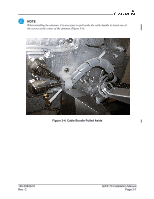
3.2 Wiring Harness Installation Allow adequate space for installation of cables and connectors. The installer shall supply and fabricate all cables. All electrical connections to the GWX 70 are made through one 78-pin D-subminiature connector. Section 4 defines the electrical characteristics of all input and output signals. Required connectors and associated hardware are supplied with the connector kit. NOTE An interfacial seal is required with each D-subminiature connector. Refer to the Jackscrew Backshell Installation Instructions (190-00313-11) for interfacial seal installation instructions. See Appendix B for examples of interconnect wiring diagrams. Construct the actual harnesses in accordance with the aircraft manufacturer authorized interconnect standards. CAUTION Check wiring connections for errors before inserting the GWX 70 into the rack. Incorrect wiring could cause internal component damage. Table 3-1. Pin Contact Part Numbers Manufacturer (Note 1) Garmin P/N Military P/N AMP Positronic 78-pin D-Subminiature 18-20 AWG 22-28 AWG 336-00044-00 N/A N/A N/A 336-00021-00 M39029/58-360 204370-02 MC8522D Table 3-2. Recommended Crimp Tools Manufacturer (Note 1) Military P/N Positronic AMP Daniels Astro Hand Crimping Tool M22520/2-01 9507 601966-1 AFM8 615717 18-20 AWG Positioner N/A 9502-11 N/A K774 N/A Insertion/ Extraction Tool (Note 2) M81969/1-04 M81969/1-04 91067-1 M81969/1-04 M81969/1-04 22-28 AWG Positioner M22520/2-09 9502-3 601966-6 K42 615725 Insertion/ Extraction Tool M81969/1-04 M81969/1-04 91067-1 M81969/1-04 M81969/1-04 GWX 70 Installation Manual Page 3-2 190-00829-01 Rev. C
-
 1
1 -
2
-
3
-
4
-
5
-
6
-
7
-
8
-
9
-
10
-
11
-
12
-
13
-
14
-
15
-
16
-
17
-
18
-
19
-
20
-
21
-
22
-
 23
23 -
 24
24 -
 25
25 -
 26
26 -
 27
27 -
 28
28 -
 29
29 -
 30
30 -
 31
31 -
 32
32 -
 33
33 -
34
-
35
-
36
-
37
-
38
-
39
-
40
-
41
-
42
-
43
-
44
-
45
-
46
-
47
-
48
-
49
-
50
-
51
-
52
-
53
-
54
-
55
-
56
-
57
-
58
-
59
-
60
-
61
-
62
-
63
-
64
-
65
 |
 |
