Garmin GWX 70 Installation Manual - Page 30
Installation, Antenna Attachment Instructions, Front View of RF Housing
 |
View all Garmin GWX 70 manuals
Add to My Manuals
Save this manual to your list of manuals |
Page 30 highlights
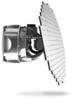
3.4 Installation The GWX 70 is designed to be rigidly mounted in the nose section of the aircraft. If the nose section is not accessible, pod mounting is possible. The bulk head or antenna mounting plate must be very close to perpendicular to the aircraft center line. The selected location must have adequate clearance for the full antenna sweep and tilt range. See Appendix A for outline and installation drawings. The nose section does not need to be pressurized. NOTE It is crucial to the performance of the GWX 70 weather radar system that care be taken in alignment of the GWX 70 unit with respect to the aircraft. 3.4.1 Antenna Attachment Instructions 1. Ensure there is no debris or obstruction in the waveguide slits of the RF housing (Figure 3-1). Figure 3-1. Front View of RF Housing GWX 70 Installation Manual Page 3-4 190-00829-01 Rev. C
-
 1
1 -
2
-
3
-
4
-
5
-
6
-
7
-
8
-
9
-
10
-
11
-
12
-
13
-
14
-
15
-
16
-
17
-
18
-
19
-
20
-
21
-
22
-
23
-
24
-
 25
25 -
 26
26 -
 27
27 -
 28
28 -
 29
29 -
 30
30 -
 31
31 -
 32
32 -
 33
33 -
 34
34 -
 35
35 -
36
-
37
-
38
-
39
-
40
-
41
-
42
-
43
-
44
-
45
-
46
-
47
-
48
-
49
-
50
-
51
-
52
-
53
-
54
-
55
-
56
-
57
-
58
-
59
-
60
-
61
-
62
-
63
-
64
-
65
 |
 |
