Garmin GWX 70 Installation Manual - Page 32
GWX 70 Installation Manual, Rev. C
 |
View all Garmin GWX 70 manuals
Add to My Manuals
Save this manual to your list of manuals |
Page 32 highlights
NOTE The horizontal and vertical position of the RF housing can be adjusted through movement of the gear positions to secure the screws in all locations. The screws can be secured in any order. 3. Secure the antenna to the outer location of the RF housing using 10 #8-32 socket head cap screws as shown in Figure 3-3. Figure 3-3. Antenna Mounting Outer Screw Locations (cables not shown for clarity) GWX 70 Installation Manual Page 3-6 190-00829-01 Rev. C
-
 1
1 -
2
-
3
-
4
-
5
-
6
-
7
-
8
-
9
-
10
-
11
-
12
-
13
-
14
-
15
-
16
-
17
-
18
-
19
-
20
-
21
-
22
-
23
-
24
-
25
-
26
-
 27
27 -
 28
28 -
 29
29 -
 30
30 -
 31
31 -
 32
32 -
 33
33 -
 34
34 -
 35
35 -
 36
36 -
 37
37 -
38
-
39
-
40
-
41
-
42
-
43
-
44
-
45
-
46
-
47
-
48
-
49
-
50
-
51
-
52
-
53
-
54
-
55
-
56
-
57
-
58
-
59
-
60
-
61
-
62
-
63
-
64
-
65
 |
 |

GWX 70 Installation Manual
190-00829-01
Page 3-6
Rev. C
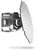
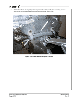
NOTE
The horizontal and vertical position of the RF housing can be adjusted through movement
of the gear positions to secure the screws in all locations. The screws can be secured in
any order.
3.
Secure the antenna to the outer location of the RF housing using 10 #8-32 socket head cap screws
as shown in Figure 3-3.
Figure 3-3. Antenna Mounting Outer Screw Locations (cables not shown for clarity)