Garmin GWX 70 Installation Manual - Page 34
GWX 70 Installation Manual, Rev. C
 |
View all Garmin GWX 70 manuals
Add to My Manuals
Save this manual to your list of manuals |
Page 34 highlights
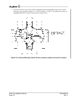
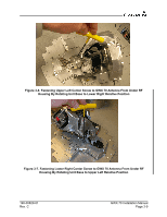
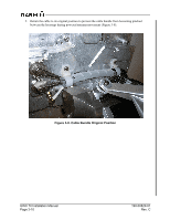
4. Secure the antenna to the center of the waveguide transition (diagonally) using 2 #6-32 socket head cap screws as shown in Figure 3-5. Refer to Figures 3-6 and 3-7 for instructions on how to manipulate the GWX 70 unit to secure the two center screws. Figure 3-5. Antenna Mounting Center Screw Locations (cables not shown for clarity) GWX 70 Installation Manual Page 3-8 190-00829-01 Rev. C
-
 1
1 -
2
-
3
-
4
-
5
-
6
-
7
-
8
-
9
-
10
-
11
-
12
-
13
-
14
-
15
-
16
-
17
-
18
-
19
-
20
-
21
-
22
-
23
-
24
-
25
-
26
-
27
-
28
-
 29
29 -
 30
30 -
 31
31 -
 32
32 -
 33
33 -
 34
34 -
 35
35 -
 36
36 -
 37
37 -
 38
38 -
 39
39 -
40
-
41
-
42
-
43
-
44
-
45
-
46
-
47
-
48
-
49
-
50
-
51
-
52
-
53
-
54
-
55
-
56
-
57
-
58
-
59
-
60
-
61
-
62
-
63
-
64
-
65
 |
 |

GWX 70 Installation Manual
190-00829-01
Page 3-8
Rev. C
4.
Secure the antenna to the center of the waveguide transition (diagonally) using 2 #6-32 socket
head cap screws as shown in Figure 3-5.
Refer to Figures 3-6 and 3-7 for instructions on how to
manipulate the GWX 70 unit to secure the two center screws.
Figure 3-5. Antenna Mounting Center Screw Locations (cables not shown for clarity)