Gateway ML6227q 8511725 - Gateway Service Guide - Page 54
Replace the four or six rubber inserts., Plug the antenna cables into the IEEE 802.11 wireless card
 |
View all Gateway ML6227q manuals
Add to My Manuals
Save this manual to your list of manuals |
Page 54 highlights
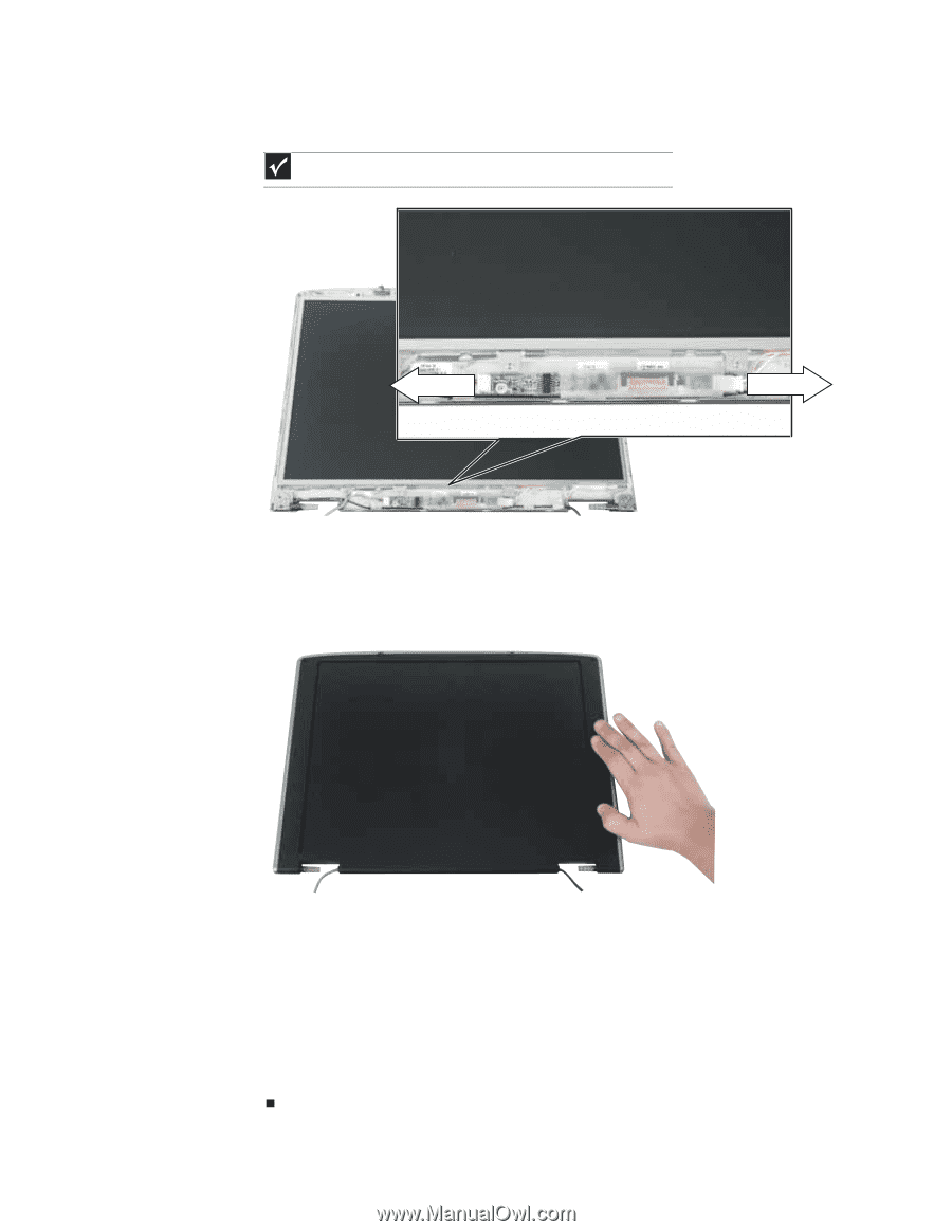
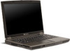
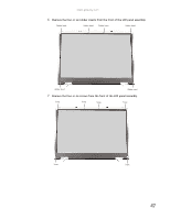
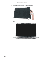
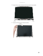
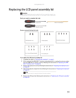
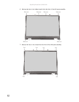
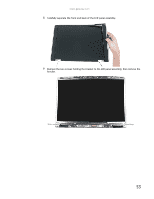
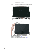
Replacing Notebook Components 12 Unplug both cables from the LCD panel inverter on the old panel, then transfer the inverter to the new panel. Plug both cables into the inverter. Important The inverter may be either at the side of the LCD panel or at the bottom. 13 Place the new LCD panel into the existing LCD panel assembly lid. 14 Replace the four screws removed in Step 10. 15 Replace the bracket and the two screws removed in Step 9. 16 Press the front and back of the LCD panel together in several places until they click in place. You should find no loose spots or spots where the two halves do not meet. 17 Replace the four or six LCD panel assembly screws. 18 Replace the four or six rubber inserts. 19 Replace the LCD panel assembly onto the notebook by following the instructions in "Replacing the LCD panel assembly" on page 38. 20 Close the keyboard compartment by following the instructions in "Replacing the keyboard" on page 31. 21 Replace the keyboard cover by following the instructions in "Replacing the keyboard cover" on page 29. 22 Plug the antenna cables into the IEEE 802.11 wireless card, then replace the wireless bay cover. 50
-
 1
1 -
2
-
3
-
4
-
5
-
6
-
7
-
8
-
9
-
10
-
11
-
12
-
13
-
14
-
15
-
16
-
17
-
18
-
19
-
20
-
21
-
22
-
23
-
24
-
25
-
26
-
27
-
28
-
29
-
30
-
31
-
32
-
33
-
34
-
35
-
36
-
37
-
38
-
39
-
40
-
41
-
42
-
43
-
44
-
45
-
46
-
47
-
48
-
 49
49 -
 50
50 -
 51
51 -
 52
52 -
 53
53 -
 54
54 -
 55
55 -
 56
56 -
 57
57 -
 58
58 -
 59
59 -
60
-
61
-
62
-
63
-
64
-
65
-
66
-
67
-
68
-
69
-
70
-
71
-
72
-
73
-
74
-
75
-
76
-
77
-
78
 |
 |