GE JS900 Installation Instructions
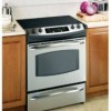
GE JS900 - Profile 30'' Slide-In Electric Range Manual
 |
View all GE JS900 manuals
Add to My Manuals
Save this manual to your list of manuals |
GE JS900 manual content summary:
- GE JS900 | Installation Instructions - Page 1
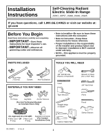
Self-Cleaning Radiant Electric Slide-In Range JSP47, JSP57, JS968, JS900, JS905 If you have questions, call 1.800.GE.CARES or visit our website at: ge.com Before You Begin Read these instructions carefully and completely. • IMPORTANT-Save these instructions for local inspector's use. • IMPORTANT - GE JS900 | Installation Instructions - Page 2
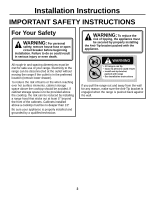
INSTRUCTIONS For Your Safety WARNING: For personal safety, remove house fuse or open circuit breaker before beginning installation. Failure to do so could result in serious injury or even death. All rough-in and spacing dimensions must be met for safe use of your range. Electricity to the range - GE JS900 | Installation Instructions - Page 3
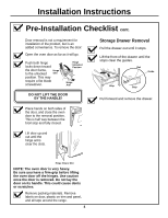
with the range.) (See page 15, section AA, for Installation Instructions) or Visit GE Web Site (See page 1) b. Call GE Answer Center (See page 1) c. Contact Dealer Move range indoors range to access the range leveling legs. Use an adjustable wrench to screw leveling legs out so that glass support - GE JS900 | Installation Instructions - Page 4
out until it stops. Lift the front of the drawer until the stops clear the guides. Rail Guide Stop Stop Pull forward and remove the drawer. Place hands on both sides of the door, and close the oven door to the removal position. This is half way between the broil stop and fully - GE JS900 | Installation Instructions - Page 5
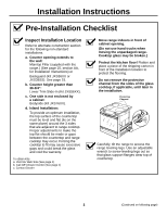
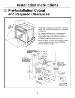
Installation Instructions 1 Pre-Installation Cutout and Required Clearances If cabinets are placed less than 30" above the range, see Alternate Construction, section AF, on page 16. 30" ranges conform to U.L. requirements for 0" spacing from vertical walls below countertops. Allow 1/4" minimum - GE JS900 | Installation Instructions - Page 6
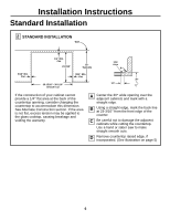
Installation Instructions Standard Installation 2 STANDARD INSTALLATION Wall 9/16" Min. Flat 1/4" Min. Flat 23-3/16" 25" Typically 9/16" Min. Flat 29-15/16"- 30-1/16" Smooth Cut Flat - GE JS900 | Installation Instructions - Page 7
a 4conductor connection to an electric range. When installing an electric range in new construction, follow Steps 3 and 5 for 4wire connection. You must use a 3-wire, single-phase A.C. 208Y/120 Volt or 240/120 Volt, 60 hertz electrical system. If the electrical service provided does not meet the - GE JS900 | Installation Instructions - Page 8
Installation Instructions Electrical Connections cont. 3 POWER CORD AND STRAIN RELIEF INSTALLATION A Remove the wire cover (on the back of the range) by removing 2 screws, using a 1/4″ nut driver. Do not discard these Wire Cover screws. B Remove the knockout ring (1-3/8″) located on bracket - GE JS900 | Installation Instructions - Page 9
Installation Instructions Electrical Connections cont. 4 3-WIRE POWER CORD INSTALLATION WARNING: The terminals of the terminal block. The 4th grounding lead must be connected to the frame of the range with the ground plate and the ground screw. A Remove the 3 lower terminal screws from the - GE JS900 | Installation Instructions - Page 10
Installation Instructions Electrical Connections cont. 6 3-WIRE CONDUIT INSTALLATION A Loosen the 3 the ground strap. DO NOT DISCARD ANY SCREWS. B Insert the ground bare wire tip between the range frame and the ground plate (removed earlier) and secure it in place with the ground screw (removed - GE JS900 | Installation Instructions - Page 11
Adjacent Cabinet FLOOR-WOOD Wall Bracket Side Rear Leveling Leg FLOOR-CONCRETE WARNING: Range must be secured by Anti-Tip bracket supplied. See instructions to install (supplied with bracket). Unless properly installed, the range could be tipped by stepping or sitting on the door. Injury may - GE JS900 | Installation Instructions - Page 12
Instructions Installing The Range cont. 11 SLIDE RANGE INTO OPENING A Position the range in front of the cabinet opening. B Make sure that the glass which overhangs the countertop clears the countertop. If necessary, raise the unit by lowering the leveling legs. C Push while lifting the range range - GE JS900 | Installation Instructions - Page 13
. SPECIAL INSTRUCTIONS IF YOU ARE HAVING PROBLEMS WHILE REPLACING THE STORAGE DRAWER If Drawer Won't Close: Drawer does not close completely Power cord may be obstructing drawer in this area Drawer front panel tipped away from body side Rear drawer support is resting on top of guide rail Remove - GE JS900 | Installation Instructions - Page 14
Instructions Final Checklist Check to make sure the circuit breaker is closed (Reset) or the circuit fuses are replaced. Be sure power is in service to If the glow is not detected within the time limit, recheck the range wiring connections. If change is required, retest again. If no change is - GE JS900 | Installation Instructions - Page 15
If you are using the optional backguard kit, refer to the backguard kit instructions for installation details. Wall Must Be 25" Level Must Be Flat 30 from damaging the painted parts. Refer to the Standard Installation of the Range beginning on page 6. Cooktop Range Maintop Filler (2) #8 Screws - GE JS900 | Installation Instructions - Page 16
approximately 30-3/8", the Vertical Side Trim Kit (JXS86XX) should be used to cover gaps between range sides and cabinet. Refer to the kit instructions for installation details. AF CABINETS OVER THE RANGE LESS THAN 30" If a 30" clearance between cooking surface and overhead combustible material or - GE JS900 | Installation Instructions - Page 17
NOTES 17 - GE JS900 | Installation Instructions - Page 18
NOTES 18 - GE JS900 | Installation Instructions - Page 19
NOTES 19 - GE JS900 | Installation Instructions - Page 20
NOTES 20
-
 1
1 -
 2
2 -
 3
3 -
 4
4 -
 5
5 -
 6
6 -
 7
7 -
8
-
9
-
10
-
11
-
12
-
13
-
14
-
15
-
16
-
17
-
18
-
19
-
20
 |
 |

1
MATERIALS YOU MAY NEED
3-Wire Cord
4
’
long
(UL Approved 40 or 50 AMP)
Lag Bolts
Anchor Sleeves
(For Anti-Tip Bracket Mounted
on Concrete Floors Only)
4-Wire Cord
4
’
long
OR
If you have questions, call 1.800.GE.CARES or visit our website at:
ge.com
Self-Cleaning Radiant
Electric Slide-In Range
Installation
Instructions
JSP47, JSP57, JS968, JS900, JS905
31-10621
07-05 JR
Before You Begin
Read these instructions carefully and completely.
•
IMPORTANT
—Save these
instructions for local inspector’s use.
•
IMPORTANT
—Observe all
governing codes and ordinances.
•
Note to Installer—Be sure to leave these
instructions with the consumer.
•
Note to Consumer—Keep these
instructions for future reference.
•
Proper installation is the responsibility
of the installer and product failure due
to improper installation is NOT covered
under warranty.
•
NOTE—This appliance must be properly
grounded.
PARTS INCLUDED
Anti-Tip Bracket
Screws
Rear Filler
2 Screws
TOOLS YOU WILL NEED
1/8
”
Drill Bit and
Electric or Hand Drill
1/4
”
Nut Driver
Level
Tape Measure
Straight Edge
or Square
Hand or Sabre Saw
Pencil
Safety Glasses
Wrench or Pliers
(for 1-7/16
”
Nut)
Pliers
Tin Snips
Squeeze Connector
(For Conduit
Installations Only)