GE JS900 Installation Instructions - Page 9
Warning
 |
View all GE JS900 manuals
Add to My Manuals
Save this manual to your list of manuals |
Page 9 highlights
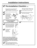
Installation Instructions Electrical Connections cont. 4 3-WIRE POWER CORD INSTALLATION WARNING: The neutral or ground wire of the power cord must be connected to the neutral terminal located in the center of the terminal block. The power leads must be connected to the lower left and the lower right terminals of the terminal block. A Remove the 3 lower terminal screws from the terminal block. Insert the 3 terminal screws through each power cord terminal ring and into the lower terminals of the terminal block. Be certain that the center wire (white/ neutral) is connected to the center lower position of the terminal block. Tighten screws securely into the terminal block. DO NOT remove the ground strap connection. Terminal block (appearance may vary) Ground plate Neutral terminal Ground strap Power cord B Skip to Step 8 and proceed with the installation. 5 4-WIRE POWER CORD INSTALLATION WARNING: The neutral wire of the supply circuit must be connected to the neutral terminal located in the lower center of the terminal block. The power leads must be connected to the lower left and the lower right terminals of the terminal block. The 4th grounding lead must be connected to the frame of the range with the ground plate and the ground screw. A Remove the 3 lower terminal screws from the terminal block. Remove the ground screw and ground plate and retain them. B Cut and discard the ground strap. DO NOT DISCARD ANY SCREWS. C Insert the one ground screw into the power cord ground wire terminal ring, through the ground plate and into the frame of the range. D Insert the 3 terminal screws (removed earlier) through each power cord terminal ring and into the lower terminals of the terminal block. Be certain that the center wire (white/ neutral) is connected to the center lower position of the terminal block. Tighten screws securely into the terminal block. Before Ground strap Terminal block or Ground strap After Terminal block Neutral terminal Ground plate (grounding to range) Ground screw E Skip to Step 8 and proceed with the installation. 9
-
 1
1 -
2
-
3
-
 4
4 -
 5
5 -
 6
6 -
 7
7 -
 8
8 -
 9
9 -
 10
10 -
 11
11 -
 12
12 -
 13
13 -
 14
14 -
15
-
16
-
17
-
18
-
19
-
20
 |
 |
