GE JS900 Installation Instructions - Page 1
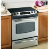
GE JS900 - Profile 30'' Slide-In Electric Range Manual
 |
View all GE JS900 manuals
Add to My Manuals
Save this manual to your list of manuals |
Page 1 highlights
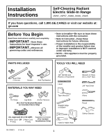
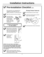
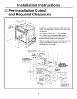
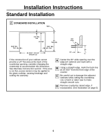
Installation Instructions Self-Cleaning Radiant Electric Slide-In Range JSP47, JSP57, JS968, JS900, JS905 If you have questions, call 1.800.GE.CARES or visit our website at: ge.com Before You Begin Read these instructions carefully and completely. • IMPORTANT-Save these instructions for local inspector's use. • IMPORTANT-Observe all governing codes and ordinances. • Note to Installer-Be sure to leave these instructions with the consumer. • Note to Consumer-Keep these instructions for future reference. • Proper installation is the responsibility of the installer and product failure due to improper installation is NOT covered under warranty. • NOTE-This appliance must be properly grounded. PARTS INCLUDED TOOLS YOU WILL NEED Rear Filler 2 Screws Screws Anti-Tip Bracket MATERIALS YOU MAY NEED Tin Snips Lag Bolts Anchor Sleeves (For Anti-Tip Bracket Mounted on Concrete Floors Only) 1/8" Drill Bit and Electric or Hand Drill Level Tape Measure Straight Edge or Square (UL Approved 40 or 50 AMP) 4-Wire Cord OR 3-Wire Cord 4' long 4' long Squeeze Connector (For Conduit Installations Only) Hand or Sabre Saw 31-10621 07-05 JR 1 Wrench or Pliers (for 1-7/16" Nut) 1/4" Nut Driver Pliers Pencil Safety Glasses
-
 1
1 -
 2
2 -
 3
3 -
 4
4 -
 5
5 -
 6
6 -
 7
7 -
8
-
9
-
10
-
11
-
12
-
13
-
14
-
15
-
16
-
17
-
18
-
19
-
20
 |
 |
