GE JS900 Installation Instructions - Page 11
Installing the Range
 |
View all GE JS900 manuals
Add to My Manuals
Save this manual to your list of manuals |
Page 11 highlights
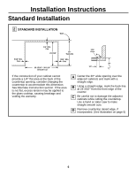
Installation Instructions Installing the Range 8 REPLACE THE WIRE COVER Replace the wire cover (on the back of the range) by replacing the 2 screws removed earlier. Wire Cover NOTE: When reinstalling the wire cover, make sure that wires do not become pinched between the wire cover and the housing. 10 INSTALLING THE BRACKET IN WOOD OR CONCRETE INSTALLATION-WOOD CONSTRUCTIONS A Locate the centers of the 4 holes identified in Fig. 1 as Floor-Wood and Wall. B Drill a 1/8" pilot hole through the pre-marked areas. Note the angle of the wall screw in Fig. 2. C Mount the Anti-Tip bracket with the 4 screws provided. 9 LOCATING THE ANTI-TIP BRACKET A Decide whether the bracket will be installed on the right or left side of the range opening. B Place the bracket as shown in Fig. 1. To Front Edge of Countertop 25" Bracket Screw Must Enter Wood or Metal FIG. 2 Wall Plate FIG. 1 Adjacent Cabinet FLOOR-WOOD Wall Bracket Side Rear Leveling Leg FLOOR-CONCRETE WARNING: Range must be secured by Anti-Tip bracket supplied. See instructions to install (supplied with bracket). Unless properly installed, the range could be tipped by stepping or sitting on the door. Injury may result from spilled hot liquids or from the range itself. A B C 11 INSTALLATION-CONCRETE CONSTRUCTIONS For concrete installation, you will need two 1/4" x 1-1/2" lag screws and two sleeve anchors. Locate the center of the 4 holes identified in Fig. 1 as Floor-Concrete and Wall. Drill the recommended size holes in each. Install the sleeve anchors into the predrilled concrete holes and install the lag and wall screws through the Anti-Tip bracket. Make sure the screws are securely tightened. (Continued on following page)
-
 1
1 -
2
-
3
-
4
-
5
-
 6
6 -
 7
7 -
 8
8 -
 9
9 -
 10
10 -
 11
11 -
 12
12 -
 13
13 -
 14
14 -
 15
15 -
 16
16 -
17
-
18
-
19
-
20
 |
 |
