Gigabyte GA-K8N ULTRA-SLI User Manual
Gigabyte GA-K8N ULTRA-SLI Manual
 |
View all Gigabyte GA-K8N ULTRA-SLI manuals
Add to My Manuals
Save this manual to your list of manuals |
Gigabyte GA-K8N ULTRA-SLI manual content summary:
- Gigabyte GA-K8N ULTRA-SLI | User Manual - Page 1
GA-K8N Ultra-SLI / GA-K8N Pro-SLI / GA-K8N-SLI AMD Socket 939 Processor Motherboard User's Manual Rev. 1004 12ME-K8NUSLI-1004 - Gigabyte GA-K8N ULTRA-SLI | User Manual - Page 2
Motherboard GA-K8N Ultra-SLI Jan. 12, 2005 Motherboard GA-K8N Ultra-SLI Jan. 12, 2005 - Gigabyte GA-K8N ULTRA-SLI | User Manual - Page 3
Motherboard GA-K8N Pro-SLI Feb. 25, 2005 Motherboard GA-K8N Pro-SLI Feb. 25, 2005 - Gigabyte GA-K8N ULTRA-SLI | User Manual - Page 4
Motherboard GA-K8N-SLI Aug. 8, 2005 Motherboard GA-K8N-SLI Aug. 8, 2005 - Gigabyte GA-K8N ULTRA-SLI | User Manual - Page 5
product information and specifications, please carefully read the "Product User Manual". „ For detailed information related to Gigabyte's unique features, please go to the "Technology Guide" section on Gigabyte's website to read or download the information you need. For more product details, please - Gigabyte GA-K8N ULTRA-SLI | User Manual - Page 6
GA-K8N Ultra-SLI / GA-K8N Pro-SLI / GA-K8N-SLI Motherboard BIOS Features 38 2-3 IntegratedPeripherals 40 2-4 Power Management Setup 44 2-5 PnP/PCI Configurations 45 2-6 PC Health Status 46 2-7 MB Intelligent Tweaker(M.I.T 49 2-8 TopPerformance 52 2-9 Load Optimized Defaults 52 2-10 Set - Gigabyte GA-K8N ULTRA-SLI | User Manual - Page 7
59 4-1 Unique Software Utilities 59 4-1-1 EasyTune 5 Introduction 59 4-1-2 Xpress Recovery2 Introduction 60 4-1-3 Flash BIOS Method Introduction 62 4-1-4 Serial ATA BIOS Setting Utility Introduction 73 4-1-5 2- / 4- / 6- / 8- Channel Audio Function Introduction 79 4-2 Troubleshooting 85 - 7 - - Gigabyte GA-K8N ULTRA-SLI | User Manual - Page 8
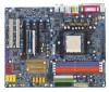
or GA-K8N Pro-SLI/GA-K8N-SLI DDR1 DDR2 DDR3 DDR4 GA-K8N Ultra-SLI / GA-K8N Pro-SLI / GA-K8N-SLI Motherboard Layout KB_MS SPDIF_I ATX_12V ATX SPDIF_O Socket 939 COMA LPT USB LAN2 IDE2 USB LAN1 AUDIO1 AUDIO2 CPU_FAN VITESSE 8201 phy F_AUDIO Marvell 8053 PCIE_1 PCIE_2 Backup Main BIOS - Gigabyte GA-K8N ULTRA-SLI | User Manual - Page 9
Marvell 8053 LAN 2 RJ45 PCI Express x 1 Bus VITESSE 8201 phy PCI Bus AMD K8 Socket 939 CPU CPUCLK+/-(200MHz) DDR 400/333/266/200MHz DIMM Dual Channel Memory Hyper Transport Bus nVIDIA® nForce4 SLI Dual BIOS 4 SATA 3Gb/s ATA33/66/100/133 IDE Channels LPC BUS IT8712 IR_CIR Floppy LPT Port COM - Gigabyte GA-K8N ULTRA-SLI | User Manual - Page 10
- 10 - - Gigabyte GA-K8N ULTRA-SLI | User Manual - Page 11
instructions below: 1. Please turn off the computer and unplug its power cord. 2. When handling the motherboard, avoid touching any metal leads or connectors. 3. It is best any installation steps or have a problem related to the use of the conditions recommended in the user manual. 3. Damage due to - Gigabyte GA-K8N ULTRA-SLI | User Manual - Page 12
1-2 Feature Summary Motherboard CPU Chipset Memory Slots IDE Connections FDD Connections Onboard SATA Peripherals Onboard LAN Onboard Audio Š GA-K8N Ultra-SLI or GA-K8N Pro-SLI or GA-K8N-SLI Š Socket 939 for AMD AthlonTM 64 / 64 FX processor (K8) Š 2000MT/s system bus Š Supports core frequencies - Gigabyte GA-K8N ULTRA-SLI | User Manual - Page 13
Supports @BIOS Supports EasyTune 5 (Note 2) Over Voltage via BIOS (CPU/ DDR/ HT-Link/ Chipset core PCI-E) Over Clock via BIOS (CPU/ PCI-E) ATX form factor; 30.5cm x 24.4cm (Note 2) EasyTune 5 functions may vary depending on different motherboards. Only for GA-K8N Ultra-SLI. Only for GA-K8N Pro - Gigabyte GA-K8N ULTRA-SLI | User Manual - Page 14
sure that the motherboard supports the CPU. 2. memory, hard drive, etc. 1-3-1 Installation of the CPU Check the processor pins to see that none are bent. Move the socket lever to the unlocked position as shown in Figure 1.(90o to the plane of the motherboard nForce4 SLI Series Motherboard - 14 - - Gigabyte GA-K8N ULTRA-SLI | User Manual - Page 15
all the fan heat sink components (Please refer to the fan heat sink manual for detailed installation instructions). Fig.2 Please connect the fan heat sink power connector to the CPU_FAN connector located on the motherboard so that the fan heat sink can properly function to prevent CPU overheating - Gigabyte GA-K8N ULTRA-SLI | User Manual - Page 16
one direction. Insert the DIMM memory module vertically into the DIMM socket. Then push it down. Fig.2 Close the plastic clip at both edges of the DIMM sockets to lock the DIMM module. Reverse the installation steps when you wish to remove the DIMM module. K8 nForce4 SLI Series Motherboard - 16 - - Gigabyte GA-K8N ULTRA-SLI | User Manual - Page 17
English Dual Channel Memory Configuration The GA-K8N Ultra-SLI/GA-K8N Pro-SLI/GA-K8N-SLI supports the Dual Channel Technology. When the Dual Channel Technology is activated, the bandwidth of memory bus will be double the original one. Due to CPU limitation, if you want to operate the Dual Channel - Gigabyte GA-K8N ULTRA-SLI | User Manual - Page 18
outlined below: 1. Read the related expansion card's instruction document before install the expansion card into the the computer, if necessary, setup BIOS utility of expansion card from BIOS. 8. Install related driver from the operating system. Installing a nForce4 SLI Series Motherboard - 18 - - Gigabyte GA-K8N ULTRA-SLI | User Manual - Page 19
section introduces steps to configure an SLI system on the GA-K8N Ulra-SLI/GA-K8N Pro-SLI/GA-K8N-SLI motherboard. Before You Begin-- I. Understanding the GIGABYTE SLI switch module: You can find an SLI switch module socket inserted with an SLI switch SLI Mode module between the first and second - Gigabyte GA-K8N ULTRA-SLI | User Manual - Page 20
English III. Supported Operating Systems: Only Windows XP operating system is currrently supported by the NVIDIA SLI technology. Enabling SLI Mode-Follow the steps below to enable SLI Mode. Note that as the switch module is inserted in the socket in the Normal Mode direction by factory default, the - Gigabyte GA-K8N ULTRA-SLI | User Manual - Page 21
fit onto the SLI gold edge included with the motherboard and secure the set Init Display First in BIOS Setup to PEG; if you plug the display cable to the card on the PCIE_16_2 slot, set Init Display First to PEG(Slot2). Graphics Card Driver Setting: Step 1: After installing graphics card driver - Gigabyte GA-K8N ULTRA-SLI | User Manual - Page 22
audio to USB keyboard, mouse, scanner, zip, speaker...etc. have a standard USB interface. Also make sure your OS supports USB controller. If your OS does not support USB controller, please contact OS vendor for possible patch or driver GA-K8N Ultra-SLI. K8 nForce4 SLI Series Motherboard - 22 - - Gigabyte GA-K8N ULTRA-SLI | User Manual - Page 23
/ IDE2 9) S_ATA0/1/2/3_SB 10) SATA0/1/2/3_SII Only for GA-K8N Ultra-SLI. 2 5 7 19 6 18 9 12 14 4 15 17 10 16 11) F_AUDIO 12) F_PANEL 13) CD_IN 14) PWR_LED 15) IR/CIR 16) F_USB1 / F_USB2/F_USB3 17) F1_1394/F2_1394 18) CLR_CMOS 19) BATTERY Only for GA-K8N Pro-SLI. - 23 - Hardware Installation - Gigabyte GA-K8N ULTRA-SLI | User Manual - Page 24
If you use a 24-pin ATX power supply, please remove the small cover on the power connector on the motherboard before plugging in the power cord ; otherwise, please do not remove it. Pin No. Definition 1 3 1 -pinATX) 24 GND(Only for 24-pin ATX) K8 nForce4 SLI Series Motherboard - 24 - - Gigabyte GA-K8N ULTRA-SLI | User Manual - Page 25
English 3/4/5) CPU_FAN / SYS_FAN/ PWR_FAN (Cooler Fan Power Connector) The cooler fan power connector supplies a +12V power voltage via a 3-pin power connector and possesses a foolproof connection design. Most coolers are designed with color-coded power connector wires. A red power connector wire - Gigabyte GA-K8N ULTRA-SLI | User Manual - Page 26
to the FDD drive. The types of FDD drives supported are: 360KB, 720KB, 1.2MB, 1.44MB and 2. set the jumper on one IDE device as Master and the other as Slave (for information on settings, please refer to the instructions located on the IDE device). 40 39 2 1 K8 nForce4 SLI Series Motherboard - Gigabyte GA-K8N ULTRA-SLI | User Manual - Page 27
, Controlled by nForce4 SLI) 10) SATA0/1/2/3_SII (SATA Connectors, Controlled by Sil3114) SATA 3Gb/s can provide up to 300MB/s transfer rate while SATA provides up to 150MB/s transfer rate. Please refer to the BIOS setting for the Serial ATA controller(s)and install the proper driver in order to - Gigabyte GA-K8N ULTRA-SLI | User Manual - Page 28
Pin 2- Pin 3: NC Pin 4: Data(-) Open: Normal Close: Reset Hardware System Open: Normal Close: Power On/Off Pin 1: LED anode(+) Pin 2: LED cathode(-) NC K8 nForce4 SLI Series Motherboard - 28 - - Gigabyte GA-K8N ULTRA-SLI | User Manual - Page 29
English 13) CD_IN (CD In Connector) Connect CD-ROM or DVD-ROM audio out to the connector. Pin No. Definition 1 1 CD-L 2 GND 3 GND 4 CD-R 14) PWR_LED PWR_LED is connect with the system power indicator to indicate whether the - Gigabyte GA-K8N ULTRA-SLI | User Manual - Page 30
the cable and connector will make the device unable to work or even damage it. For optional front USB cable, please contact your local dealer. 2 10 1 9 Pin No. 1 2 3 4 5 6 7 8 9 10 Definition Power Power USB DXUSB DyUSB DX+ USB Dy+ GND GND No Pin NC K8 nForce4 SLI Series Motherboard - 30 - - Gigabyte GA-K8N ULTRA-SLI | User Manual - Page 31
17) F1_1394/F2_1394 (IEEE 1394 Connectors) Serial interface standard set by Institute of Electrical and Electronics Engineers, which has features improper use of this header. Open: Normal 1 Short: Clear CMOS 1 Only for GA-K8N Ultra-SLI. Only for GA-K8N Pro-SLI. - 31 - Hardware Installation - Gigabyte GA-K8N ULTRA-SLI | User Manual - Page 32
the battery gently and put it aside for about 10 minutes. (Or you can use a metal object to connect the positive and negative pins in the battery holder to makethem short for one minute.) 3. Re-install the battery. 4. Plug the power cord and turn ON the computer. K8 nForce4 SLI Series Motherboard - Gigabyte GA-K8N ULTRA-SLI | User Manual - Page 33
the possible selections for the highlighted item. To exit the Help Window press . Because BIOS flashing is potentially risky, please do it with caution and avoid inadequate operation that may result in system malfunction. Only for GA-K8N Ultra-SLI. Only for GA-K8N Pro-SLI. - 33 - BIOS Setup - Gigabyte GA-K8N ULTRA-SLI | User Manual - Page 34
and may differ from the exact settings for your motherboard. The Main Menu (For example: BIOS Ver. : F6a) Once you enter Award BIOS CMOS Setup Utility, the Main be in best performance configuration. Only for GA-K8N Ultra-SLI. Only for GA-K8N Pro-SLI. K8 nForce4 SLI Series Motherboard - 34 - Gigabyte GA-K8N ULTRA-SLI | User Manual - Page 35
allows you to limit access to the system and Setup, or just to Setup. „ Set User Password Change, set, or disable password. It allows you to limit access to the system. „ Save & Exit Setup Save CMOS value settings to CMOS and exit setup. „ Exit Without Saving Abandon all CMOS value changes and exit - Gigabyte GA-K8N ULTRA-SLI | User Manual - Page 36
detect SATA IDE devices during POST. (Default value) None Select this if no SATA IDE devices are used and the system will skip the automatic detection step and allow for faster system start up. Capacity Capacity of currently installed hard disk. K8 nForce4 SLI Series Motherboard - 36 - Gigabyte GA-K8N ULTRA-SLI | User Manual - Page 37
be prompted. Whenever the BIOS detects a non-fatal error the system will be stopped. All, But Keyboard The system boot will not stop for a But Disk/Key The system boot will not stop for a keyboard or disk error; it will stop for all other errors. Floppy 3 Mode Support (for Japan Area) Disabled - Gigabyte GA-K8N ULTRA-SLI | User Manual - Page 38
BIOS can not tell from 720K, 1.2M or 1.44M drive type as they are all 80 tracks. Disabled BIOS will not search for the type of floppy disk drive by track number. Note that there will not be any warning message if the drive installed is 360K. (Default value) K8 nForce4 SLI Series Motherboard - Gigabyte GA-K8N ULTRA-SLI | User Manual - Page 39
Setup correct password is not entered at the prompt. The system will boot, but access to Setup will be denied if the correct password the motherboard. PEG Set Init display first to PCI Express VGA card (PCIE_16_1). (Default value) PCI slot Set Init display first to PCI. PEG (Slot2) Set Init - Gigabyte GA-K8N ULTRA-SLI | User Manual - Page 40
Integrated Peripherals USB Memory Type AC97 Audio Onboard 139412 Onboard LAN control1 OnBoard LAN Boot ROM1 SATA RAID-5/ATA controller1 SATA controller Function1 this function. F1: General Help Only for GA-K8N Ultra-SLI. Only for GA-K8N Pro-SLI. K8 nForce4 SLI Series Motherboard - 40 - - Gigabyte GA-K8N ULTRA-SLI | User Manual - Page 41
value) Disable Serial ATA 2 supported. (Note) When using driver version 1.2, please enable "NV IDE/SATA RAID function" if you wish to create RAID data drive or install O.S. on the RAID drive. And manually set "NV SATA1/NV SATA 2 class code" from 0101 to 0104. If your SATA hard drive is connected - Gigabyte GA-K8N ULTRA-SLI | User Manual - Page 42
is connected to the SATA0 or SATA1 connector , please set "NV SATA1 class code" to 0104. If your SATA hard drive is connected to the SATA2 or SATA3 connector , please set "NV SATA2 class code" to 0104. Only for GA-K8N Ultra-SLI. Only for GA-K8N Pro-SLI. K8 nForce4 SLI Series Motherboard - 42 - - Gigabyte GA-K8N ULTRA-SLI | User Manual - Page 43
. Legacy USB Keyboard/Storage Enabled Disabled Enable USB keyboard support in the MS-DOS environment. Disable this function. (Default value) Legacy (DOS) USB Mouse Enabled Enable USB mouse support in the MS-DOS environment. Disabled Disable this function. (Default value) - 43 - BIOS Setup - Gigabyte GA-K8N ULTRA-SLI | User Manual - Page 44
Up Modem Ring On USB Resume from Suspend Power- set "Resume by Alarm" item to enabled and key in Date/Time to power on system. Disabled Disable this function. (Default value) Enabled Enable alarm function to POWER ON system. If Power-On by Alarm is Enabled. K8 nForce4 SLI Series Motherboard - Gigabyte GA-K8N ULTRA-SLI | User Manual - Page 45
. (Default value) Enter from 1 to 5 characters to set the Keyboard Power On Password. Any KEY Press any key set at Password, you can set the password here. Enter Input password (from 1 to 5 characters) and press Enter to set the value) Set IRQ 3,4,5,7,9,10,11,12,14,15 to PCI 2. Auto assign IRQ - Gigabyte GA-K8N ULTRA-SLI | User Manual - Page 46
OK OK 34oC 3183 RPM 0 RPM 0 RPM [Disabled] [Disabled] [Disabled] Item Help Menu Level CPU FAN Manual Control x CPU FAN: Low speed x CPU FAN: Mid speed x CPU FAN: High speed x Temp of FAN both CPU Smart FAN Control and CPU FAN Manual Control are disabled. K8 nForce4 SLI Series Motherboard - 46 - - Gigabyte GA-K8N ULTRA-SLI | User Manual - Page 47
manual control function. Disabled Disable the CPU fan manual control function. (Default value) CPU FAN: Low Speed Set Mid Speed Set the parameter temperature set in High Speed Set the temperature set in Manual Control are disabled. (Note) Whether the CPU Smart FAN Control function is supported - Gigabyte GA-K8N ULTRA-SLI | User Manual - Page 48
Limit of High Speed (Default temperature: 60oC) When the CPU temperature exceeds the value set in this option, the CPU fan rotates with the parameter specified in CPU FAN: CPU temperature exceeds the value set in this option, the CPU fan runs at full speed. K8 nForce4 SLI Series Motherboard - 48 - - Gigabyte GA-K8N ULTRA-SLI | User Manual - Page 49
system broken. For power end-user use only. HT Frequency ratio Set HT Frequency ratio to 1x, 1.5x, 2x, 2.5x, 3x, 4x, or 5x. (Default: Auto ) CPU Frequency 200 ~ 456 Set CPU frequency from 200Mhz to 456Mhz. K8 CPU Clock Ratio This setup option will - Gigabyte GA-K8N ULTRA-SLI | User Manual - Page 50
bus clock Set Write Recovery Time to 2 bus clock. (Default value) Set Write Recovery Time to 3 bus clock. Write-to-Read Delay (Twtr) 1 bus clock Set Write-to-Read Delay to 1 bus clock. (Default value) 2 bus clock Set Write-to-Read Delay to 2 bus clock. K8 nForce4 SLI Series Motherboard - 50 - Gigabyte GA-K8N ULTRA-SLI | User Manual - Page 51
performance. Auto Set Robust Graphics Booster to Auto. (Default value) Fast Set Robust Graphics Booster to Fast. Turbo Set Robust Graphics Booster to Turbo. CPU Voltage Control Supports adjustable CPU +0.1v +0.2v Increase DDR voltage +0.1V. Increase DDR voltage +0.2V. - 51 - BIOS Setup - Gigabyte GA-K8N ULTRA-SLI | User Manual - Page 52
with Windows XP, but works smoothly with Windows NT. Therefore, if your system is not perform enough, the reliability or stability problem will BIOS and Chipset Features which the system automatically detects. Only for GA-K8N Ultra-SLI. Only for GA-K8N Pro-SLI. K8 nForce4 SLI Series Motherboard - Gigabyte GA-K8N ULTRA-SLI | User Manual - Page 53
Once the password is disabled, the system will boot and you can enter Setup freely. The BIOS Setup program allows you to specify two separate in Advance BIOS Features Menu, you will be prompted only when you try to enter Setup. Only for GA-K8N Ultra-SLI. Only for GA-K8N Pro-SLI. - 53 - BIOS Setup - Gigabyte GA-K8N ULTRA-SLI | User Manual - Page 54
BIOS Features Integrated Peripherals Power Management Setup PnP/PCI Configurations PC Health Status MB Intelligent Tweaker(M.I.T.) Top Performance Load Optimized Defaults Set return to Setup Utility. Only for GA-K8N Ultra-SLI. Only for GA-K8N Pro-SLI. K8 nForce4 SLI Series Motherboard - 54 - - Gigabyte GA-K8N ULTRA-SLI | User Manual - Page 55
use Windows Service Pack. After install Windows Service Pack, it will show a question mark "?" in "Universal Serial Bus controller" under "Device Manager". Please remove the question mark and restart the system (System will auto-detect the right USB2.0 driver). Only for GA-K8N Ultra-SLI. - 55 - Gigabyte GA-K8N ULTRA-SLI | User Manual - Page 56
some free software, you can choose anyone you want and press "install" to install them. 1 3-3 Software Information This page lists the contents of software and drivers in this CD-title. Only for GA-K8N Ultra-SLI. K8 nForce4 SLI Series Motherboard - 56 - - Gigabyte GA-K8N ULTRA-SLI | User Manual - Page 57
English 3-4 Hardware Information This page lists all device you have for this motherboard. 3-5 Contact Us Please see the last page for details. - 57 - Drivers Installation - Gigabyte GA-K8N ULTRA-SLI | User Manual - Page 58
English K8 nForce4 SLI Series Motherboard - 58 - - Gigabyte GA-K8N ULTRA-SLI | User Manual - Page 59
5 presents the most convenient Windows based system performance enhancement and manageability utility. Featuring several powerful yet easy to use tools such as 1) Overclocking for enhancing system performance, 2) C.I.A. and M.I.B. for special enhancement for CPU and Memory, 3) Smart-Fan control for - Gigabyte GA-K8N ULTRA-SLI | User Manual - Page 60
CD/DVD: Press any key to startup XpressRecovery2..... Boot from CD/DVD: Award Modular BIOS v6.00PG, An Energy Star Ally Copyright (C) 1984-2005, Award Software, Inc. GA-K8N Ultra-SLI F7b . . . . :BIOS Setup/Dual BIOS, : Xpress Recovery2, For Boot Menu 03/03/2006-NF-CK804-6A61FG0DC-00 - Gigabyte GA-K8N ULTRA-SLI | User Manual - Page 61
SATA hard disks on the following motherboards (As this is a BIOS-related issue, it can be solved by BIOS update) GA-K8U GA-K8U-9 GA-K8NXP-SLI GA-K8N Ultra-SLI GA-K8N Pro-SLI GA-K8NXP-9 GA-K8N Ultra-9 GA-K8NF-9 (PCB Ver. 1.0) GA-K8NE (PCB Ver. 1.0) GA-K8NMF-9 - 61 - GA-8N-SLI Royal GA-8N-SLI Pro - Gigabyte GA-K8N ULTRA-SLI | User Manual - Page 62
CMOS Q-Flash Utility Update Main BIOS from Floppy Update Backup BIOS from Floppy Save Main BIOS to Floppy Save Backup BIOS to Floppy PgDn/PgUp: Modify : Move ESC: Reset 512K 512K F10: Power Off Only for GA-K8N Ultra-SLI. Only for GA-K8N Pro-SLI. K8 nForce4 SLI Series Motherboard - 62 - - Gigabyte GA-K8N ULTRA-SLI | User Manual - Page 63
Error : Disable(Default), Enable If the BIOS occurs a checksum error or the Main BIOS occurs a WIDE RANGE PROTECTION error and Halt On Error set to Enable, the PC will show messages on the boot screen, and the system will pause and wait for the user's instruction. If Auto Recovery :Disable, it will - Gigabyte GA-K8N ULTRA-SLI | User Manual - Page 64
with dual BIOS. In the BIOS menu of the motherboards supporting Q-Flash and Dual BIOS, the Q-Flash utility and Dual BIOS utility are combined in the same screen. This section only deals with how to use Q-Flash utility. In the following sections, we take GA-8KNXP Ultra as the example to guide you how - Gigabyte GA-K8N ULTRA-SLI | User Manual - Page 65
Wide Range Protection Disable Boot From Main Bios Auto Recovery Enable Halt On Error Disable Copy Main ROM Data to Backup Load Default Settings Save Settings to CMOS Q-Flash Utility Load Main BIOS from Floppy Load Backup BIOS from Floppy Save Main BIOS to Floppy Save Backup BIOS to Floppy Enter - Gigabyte GA-K8N ULTRA-SLI | User Manual - Page 66
Main BIOS to Floppy Save Backup BIOS to Floppy Enter : Run :Move ESC:Reset F10:Power Off Do not trun off power or reset your system at this stage!! After BIOS file is read, you'll see a confirmation dialog box asking you "Are you sure to update BIOS?" K8 nForce4 SLI Series Motherboard - 66 - Gigabyte GA-K8N ULTRA-SLI | User Manual - Page 67
system reboots, you may find the BIOS version on your boot screen becomes the one you flashed. The BIOS file becomes Fba after updating. Award Modular BIOS v6.00PG, An Energy Star Ally Copyright (C) 1984-2003, Award Software, Inc. Intel i875P AGPset BIOS for 8KNXP Ultra Fba Check System Health OK - Gigabyte GA-K8N ULTRA-SLI | User Manual - Page 68
Disk Type... Press Y on your keyboard to save and exit. Part Two: Updating BIOS with Q-FlashTM Utility on Single-BIOS Motherboards. This part guides users of single-BIOS motherboards how to update BIOS using the Q-FlashTM utility. CMOS Setup Utility-Copyright (C) 1984-2004 Award Software Standard - Gigabyte GA-K8N ULTRA-SLI | User Manual - Page 69
Q-FlashTM utility Enter : Run Keep DMI Data Enable Update BIOS from Floppy Save BIOS to Floppy :Move ESC:Reset F10:Power Off Action download one BIOS file to the floppy disk so only one BIOS file, 8GE800.F4, is listed. Please confirm again you have the correct BIOS file for your motherboard - Gigabyte GA-K8N ULTRA-SLI | User Manual - Page 70
/2003-I845GE-6A69YG01C-00 6. Press Del to enter BIOS menu after system reboots and "Load BIOS Fail-Safe Defaults". See how to Load BIOS Fail-Safe Defaults, please kindly refer to Step 6 to 7 in Part One. Congratulation!! You have updated BIOS successfully!! K8 nForce4 SLI Series Motherboard - 70 - - Gigabyte GA-K8N ULTRA-SLI | User Manual - Page 71
Select @BIOSTM sever. d. Select the exact model name on your motherboard. e. System will automatically download and update the BIOS. II. Update BIOS NOT through Internet: a. Do not click "Internet Update" icon. b. Click "Update New BIOS". c. Please select "All Files" in dialog box while opening the - Gigabyte GA-K8N ULTRA-SLI | User Manual - Page 72
, please go onto Gigabyte's website for downloading and updating it according to method II. IV. Please note that any interruption during updating will cause system unbooted. V. Do not use @BIOS and C.O.M. (Corporate Online Management) at the same time. K8 nForce4 SLI Series Motherboard - 72 - - Gigabyte GA-K8N ULTRA-SLI | User Manual - Page 73
English 4-1-4 Serial ATA BIOS Setting Utility Introduction RAID Levels RAID (Redundant Array of Independent Disks) is a method implementation costs. The RAID levels which the nVIDIA® nForce4 SLI chipset supports are RAID 0, RAID 1, RAID 0+RAID 1 and JBOD. RAID 0 (Striping) RAID 0 reads and writes - Gigabyte GA-K8N ULTRA-SLI | User Manual - Page 74
more detailed setup information, please visit "Support\ Motherboard\ Technology Guide section" on our website at http:\\www.gigabyte.com.tw to read or download the information you need.) Configuring the Nvidia RAID BIOS The NVRAID BIOS setup lets you choose the RAID array type and which hard drives - Gigabyte GA-K8N ULTRA-SLI | User Manual - Page 75
Window If necessary, press the tab key to move from field to field until the appropriate field is highlighted. Selecting the RAID Mode By default, this is set to Mirroring. To change to a different RAID that you enabled from the RAID Config BIOS setup page appear in the Free Disks block. These are - Gigabyte GA-K8N ULTRA-SLI | User Manual - Page 76
select the array, then press B to specify the array as bootable. Boot No NVIDIA RAID Utility Nov 5 2004 - Array List - Id Status Vendor Array Model Name 2 Healthy NVIDIA MIRROR 111.79G [Ctrl-X] Exit [ ] Select [B] Set Boot [N] New Array [ENTER] Detail K8 nForce4 SLI Series Motherboard - 76 - - Gigabyte GA-K8N ULTRA-SLI | User Manual - Page 77
Y to wipe out all the data, otherwise press N. Press Enter again to go back to the previous screen and then press Ctrl + X to exit the RAID setup. Now that the RAID setup has been configured from the RAID BIOS, the next step is to configure and load drivers under Windows. - 77 - Appendix - Gigabyte GA-K8N ULTRA-SLI | User Manual - Page 78
system to SATA hard disks on the Sil3114 controller, you must select the Sil3114 Raid5 item. Please refer to the provided Sil3114 SATA RAID (RAID 5) function manual for detailed information about Sil3114 SATA RAID configuration. Only for GA-K8N Ultra-SLI. K8 nForce4 SLI Series Motherboard - 78 - Gigabyte GA-K8N ULTRA-SLI | User Manual - Page 79
in Windows XP) Stereo Speakers Connection and Settings: We recommend that you use the speaker with amplifier to acquire the best sound effect if the stereo output is applied. STEP 1: Connect the stereo speakers or earphone to "Line Out". Line Out STEP 2 : Following installation of the audio driver - Gigabyte GA-K8N ULTRA-SLI | User Manual - Page 80
of the audio driver, you find a Sound Effect icon on the lower right hand taskbar. Click the icon to select the function. STEP 3: Click "Speaker Configuration" then click on the left selection bar and select "4CH Speaker" to complete 4 channel audio configuration. K8 nForce4 SLI Series Motherboard - Gigabyte GA-K8N ULTRA-SLI | User Manual - Page 81
the rear channels to "Rear Speaker Out", and the Center/Subwoofer channels to "Center/Subwoofer Speaker Out". STEP 2 : Following installation of the audio driver, you find a Sound Effect icon on the lower right hand taskbar. Click the icon to select the function. STEP 3: Click "Speaker Configuration - Gigabyte GA-K8N ULTRA-SLI | User Manual - Page 82
Following installation of the audio driver, you find a audio configuration. Sound Effect Configuration: At the sound effect menu, users can adjust sound option settings as desired. Front Speaker Out Center/Subwoofer Speaker Out Rear Speaker Out Side Speaker Out K8 nForce4 SLI Series Motherboard - Gigabyte GA-K8N ULTRA-SLI | User Manual - Page 83
DirectX8.1 or later version before to enable Jack-Sensing support for Windows 98/ 98SE/ 2000/ ME. Jack-Sensing includes 2 parts: AUTO and MANUAL. Following is an example for 2 channels (Following pictures are in Windows XP): Introduction of audio connectors You may connect CDROM, Walkman or others - Gigabyte GA-K8N ULTRA-SLI | User Manual - Page 84
English If you set wrong with the connectors, the warning message will come out as right picture. Manual setting: If the device picture shows different from what you set, please press "Manual Selection" to set. K8 nForce4 SLI Series Motherboard - 84 - - Gigabyte GA-K8N ULTRA-SLI | User Manual - Page 85
English 4-2 Troubleshooting Below is a collection of general asked questions. To check general asked questions based on a specific motherboard model, please log on to www.gigabyte.com.tw Question 1: I cannot see some options that were included in previous BIOS after updating BIOS. Why? Answer: - Gigabyte GA-K8N ULTRA-SLI | User Manual - Page 86
English K8 nForce4 SLI Series Motherboard - 86 - - Gigabyte GA-K8N ULTRA-SLI | User Manual - Page 87
Bau Chiang Road, Hsin-Tien, Taipei 231, Taiwan TEL: +886-2-8912-4888 FAX: +886-2-8912-4003 Tech. Support : http://tw.giga-byte.com/TechSupport/ServiceCenter.htm Non-Tech. Support(Sales/Marketing) : http://ggts.gigabyte.com.tw/nontech.asp WEB address (English): http://www.gigabyte.com.tw WEB address - Gigabyte GA-K8N ULTRA-SLI | User Manual - Page 88
Representative Office Of GIGA-BYTE Technology Co., Ltd. in Romania Tech. Support : http://tw.giga-byte.com/TechSupport/ServiceCenter.htm Non-Tech. Support(Sales/Marketing) : http://ggts.gigabyte.com.tw/nontech.asp WEB address: http://www.gigabyte.com.ro K8 nForce4 SLI Series Motherboard - 88 -
-
 1
1 -
 2
2 -
 3
3 -
 4
4 -
 5
5 -
 6
6 -
 7
7 -
8
-
9
-
10
-
11
-
12
-
13
-
14
-
15
-
16
-
17
-
18
-
19
-
20
-
21
-
22
-
23
-
24
-
25
-
26
-
27
-
28
-
29
-
30
-
31
-
32
-
33
-
34
-
35
-
36
-
37
-
38
-
39
-
40
-
41
-
42
-
43
-
44
-
45
-
46
-
47
-
48
-
49
-
50
-
51
-
52
-
53
-
54
-
55
-
56
-
57
-
58
-
59
-
60
-
61
-
62
-
63
-
64
-
65
-
66
-
67
-
68
-
69
-
70
-
71
-
72
-
73
-
74
-
75
-
76
-
77
-
78
-
79
-
80
-
81
-
82
-
83
-
84
-
85
-
86
-
87
-
88
 |
 |

GA-K8N Ultra-SLI /
GA-K8N Pro-SLI /
GA-K8N-SLI
AMD Socket 939 Processor Motherboard
User's Manual
Rev. 1004
12ME-K8NUSLI-1004