Gigabyte GA-K8N ULTRA-SLI User Manual - Page 19
Setup of SLI Scalable Link Interface Configuration - chipset
 |
View all Gigabyte GA-K8N ULTRA-SLI manuals
Add to My Manuals
Save this manual to your list of manuals |
Page 19 highlights
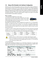
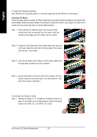
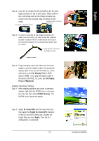
English 1-6 Setup of SLI (Scalable Link Interface) Configuration NVIDIA nForce4 SLI offers blistering graphics performance with the ability to bridge two NVIDIA SLIready PCI ExpressTM graphics cards! The SLI design takes advantage of the increased bandwidth of the PCI ExpressTM bus architecture, features hardware and software innovations within NVIDIA GPU (graphics processing unit) and the NVIDIA nForce4 chipset. Together, the NVIDIA SLI technologies work seamlessly to allow two graphics cards to operate in parallel and share the work and deliver heartpounding PC performance. This section introduces steps to configure an SLI system on the GA-K8N Ulra-SLI/GA-K8N Pro-SLI/GA-K8N-SLI motherboard. Before You Begin-- I. Understanding the GIGABYTE SLI switch module: You can find an SLI switch module socket inserted with an SLI switch SLI Mode module between the first and second PCIE x 16 slots. The SLI switch module has gold edge connectors on the top and bottom of it. One connector is SLI Mode and the other is Normal Mode. Normal Mode Normal Mode: Only the first PCIE x 16 slot is available and can operate at up to x 16 in Normal Mode. SLI Mode: In SLI Mode, the two PCIE x 16 slots can run in two modes. You can either use them as two individual x 8 slots or install two SLI-ready PCIE x 16 cards (Example: GIGABYTE GV-NX66T128D) of the same model and link them together with an SLI bridge connector to enable SLI function to provide enhanced performance. To change to a mode, you need to insert the swtich module into the switch socket with the gold edge connector on the top. As not all PCIE slots are available while in SLI or Normal Mode, please refer to the table below to check PCIE slots available in SLI or Normal Mode before installation. SLI Mode Normal Mode PCIE_1 Available Available PCIE_16_1 Available* Available PCIE_2 Not available Available PCIE_16_2 Available* Not available "*" can run at up to PCIE x 8 mode. 1. Installing a device to a PCIE slot when it's not available might damage the system. 2. We do not recommend removing the SLI switch module from the motherboard because in that case, all PCIE slots will not be available except for the PCIE_16_1 slot, and the slot can be used only as a PCIE x 8 slot. II. Power Requirements: The exact power requirements will depend on your overall system configurations. You need a power supply that can provide sufficient and stable power to your system and the two SLI graphics cards. Please refer to the table below to check recommended power for different systems. - 19 - Hardware Installation
-
 1
1 -
2
-
3
-
4
-
5
-
6
-
7
-
8
-
9
-
10
-
11
-
12
-
13
-
 14
14 -
 15
15 -
 16
16 -
 17
17 -
 18
18 -
 19
19 -
 20
20 -
 21
21 -
 22
22 -
 23
23 -
 24
24 -
25
-
26
-
27
-
28
-
29
-
30
-
31
-
32
-
33
-
34
-
35
-
36
-
37
-
38
-
39
-
40
-
41
-
42
-
43
-
44
-
45
-
46
-
47
-
48
-
49
-
50
-
51
-
52
-
53
-
54
-
55
-
56
-
57
-
58
-
59
-
60
-
61
-
62
-
63
-
64
-
65
-
66
-
67
-
68
-
69
-
70
-
71
-
72
-
73
-
74
-
75
-
76
-
77
-
78
-
79
-
80
-
81
-
82
-
83
-
84
-
85
-
86
-
87
-
88
 |
 |
