Hayward TriStar XL HCP3000 Series Variable Speed Pump - Owners Manual - Page 10
A, B, C
 |
View all Hayward TriStar XL manuals
Add to My Manuals
Save this manual to your list of manuals |
Page 10 highlights
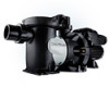
the left side conduit openings on the motor drive and through the slot provided on the backside of the wall mount plate, SP3200DR10. Use a liquid tight cordgrip, appropriately sized for the cable being used, to seal the conduit opening. Cable used may be up to 500 feet in length. (Figure C) 8. Mount the user interface to the wall mount plate, SP3200DR10, using the two screws. (Figure C) 9. Reinstall the wiring compartment cover, taking care to make sure it is properly aligned with the motor drive, and tighten the three screws to secure. 10. Install the blank cover, SP3200DR9, on the motor drive in the desired orientation. This cover is important to protect internal electronics. (Figure B) 11. Apply power to the system and resume normal operation. The following diagrams illustrate the interface wall mounting procedure: Figure A Remove the Digital Control Interface for Wall Mounting Figure B Attach the blank cover onto the pump. Figure C 9 USE ONLY HAYWARD GENUINE REPLACEMENT PARTS
-
 1
1 -
2
-
3
-
4
-
 5
5 -
 6
6 -
 7
7 -
 8
8 -
 9
9 -
 10
10 -
 11
11 -
 12
12 -
 13
13 -
 14
14 -
 15
15 -
16
-
17
-
18
-
19
-
20
-
21
-
22
-
23
-
24
-
25
-
26
-
27
-
28
 |
 |
