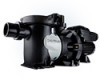
Hayward TriStar XL HCP3000 Series Variable Speed Pump - Owners Manual - Page 9
Digital Control Interface Orientation, Interface Wall Mounting
 |
View all Hayward TriStar XL manuals
Add to My Manuals
Save this manual to your list of manuals |
Page 9 highlights
Remote Control Wiring/Operation The HCP3000 Series VS pump family can be controlled in a wide variety of ways as described below: 1. They can operate by themselves in Stand-Alone Mode using their built-in programmable timers. 2. They can also be controlled from third party controls (i.e. another manufacturer's control) and Hayward controls that are not software compatible using relay contacts. See page 12 for more information regarding connecting this pump and third party/non-software compatible Hayward controls. 3. They can communicate with and be controlled by Hayward pool and spa controls. See page 13 for more information regarding connecting this pump and Hayward pool and spa controls. Digital Control Interface Orientation The Digital Control Interface can be rotated to any of four desired positions after installation by loosening the two screws securing the user interface to the motor drive, lifting the user interface and rotating it to the desired position, and tightening the two screws in the new position. Interface Wall Mounting The interface can also be wall mounted using the parts supplied in the optional wall mount kit using the following procedure. Refer to the diagram on Page 9. 1. TURN OFF THE ELECTRICAL POWER AT THE CIRCUIT BREAKER. 2. Loosen the two screws securing the user interface to the motor drive and remove the user interface. (Figure A) 3. Disconnect the short cable that extends out from the motor drive to the user interface. (Figure A) 4. Loosen the three screws securing the wiring compartment cover to the motor drive and remove the cover to gain access to the drive wiring compartment. 5. Unplug the short cable from the RS485 terminal block on the low voltage PCB. 6. Mount the wall mount plate, SP3200DR10, in the desired location. (Figure C) 7. Connect the interface cable as shown in the Wall Mounted Digital Control Interface Wiring diagram shown on page 13 to the second motor drive RS485 terminal block and user interface PCB. Use multi-conductor, jacketed cable suitable for the installation location. The cable must be routed through one of 8 USE ONLY HAYWARD GENUINE REPLACEMENT PARTS
-
 1
1 -
2
-
3
-
 4
4 -
 5
5 -
 6
6 -
 7
7 -
 8
8 -
 9
9 -
 10
10 -
 11
11 -
 12
12 -
 13
13 -
 14
14 -
15
-
16
-
17
-
18
-
19
-
20
-
21
-
22
-
23
-
24
-
25
-
26
-
27
-
28
 |
 |
