HealthRider E730 Elliptical Canadian English Manual - Page 5
Slide an M8 Split Washer 85 and an M8 Washer
 |
View all HealthRider E730 Elliptical manuals
Add to My Manuals
Save this manual to your list of manuals |
Page 5 highlights
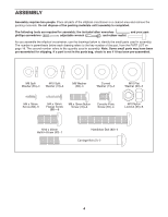
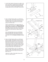
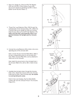
1. Hold the Rear Stabilizer (4) against the saddle on the 1 rear of the Frame (1). Make sure that the Rear Stabi- liser is turned so the square holes are facing away from the Frame. Attach the Rear Stabilizer with two 55 Carriage Bolts (2) and two M10 Nylon Locknuts (55). 55 1 4 2 2. Slide an M8 Split Washer (85) and an M8 Washer (89) onto an M8 x 19mm Button Screw (76). Thread the Button Screw into one end of an Incline Axle (15). Next, apply a small amount of the included grease to the Incline Axle. Align the indicated tubes on the Incline Frame (7) with the tubes on the Frame (1). Make sure that the Incline Frame is turned so the V-shaped grooves are on top. Insert the Incline Axle (15) through the Incline Frame and the Frame. Note: It may be helpful to tap the Incline Axle with a rubber mallet to insert it. Slide an M8 Split Washer (85) and an M8 Washer (89) onto another M8 x 19mm Button Screw (76). Thread the Button Screw into the open end of the Incline Axle (15). Do not tighten the Button Screws yet. 3. Slide an M8 Split Washer (85) and an M8 Washer (89) onto an M8 x 19mm Button Screw (76). Next, thread the Button Screw into one end of the Incline Motor Axle (14). With the help of a second person, raise the Incline Frame (7). Insert the Incline Motor Axle through one side of the Incline Frame, through a Plastic Spacer (91), through the end of the motor screw, through another Plastic Spacer (91), and through the other side of the Incline Frame. Slide an M8 Split Washer (85) and an M8 Washer (89) onto an M8 x 19mm Button Screw (76). Thread the Button Screw into the open end of the Incline Motor Axle (14). Tighten the four M8 x 19mm Button Screws (76) used in this step and step 2. 2 Grease 15 89 85 V-shaped Groove 7 85 89 76 Tubes 76 3 1 Tubes 85 14 89 76 Motor Screw 85 76 89 91 7 5
-
 1
1 -
 2
2 -
 3
3 -
 4
4 -
 5
5 -
 6
6 -
 7
7 -
 8
8 -
 9
9 -
 10
10 -
 11
11 -
12
-
13
-
14
-
15
-
16
-
17
-
18
-
19
-
20
 |
 |
