HP 2000fc HP StorageWorks 2012fc Modular Smart Array user guide (481597-001, M - Page 16
Table 1-4, Location, Port/Switch, Description
 |
View all HP 2000fc manuals
Add to My Manuals
Save this manual to your list of manuals |
Page 16 highlights
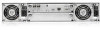
Figure 1-2 shows the ports and switches at the back of the controller. Power switch LINK SPEED LINK SPEED FC Port 0 FC Port 1 LINK SPEED LINK SPEED FC Port 0 FC Port 1 Service DIRTY CLEAN CACHE ACTIVITY Service CLI 10/100 BASE-T DIRTY CLEAN CACHE ACTIVITY CLI 10/100 BASE-T STATUS STATUS Host ports Service port CLI port Figure 1-2 Controller Ports and Switches (Back View) Ethernet port Expansion port Table 1-4 describes the ports and switches on the back of the controller. Table 1-4 Controller Ports and Switches (Back) Location Port/Switch Description Power and Power switch Toggle, where: cooling • - is On module • O is Off Controller Host ports module 4-Gbps FC ports used to connect to data hosts. Each port contains a Small Form-factor Pluggable (SFP) transceiver. Host port 0 and 1 correspond to host channel 0 and 1, respectively. Controller Expansion module port 3-Gbps, 4-lane (12 Gbps total) table-routed SAS Out port used to connect drive enclosures. Controller Ethernet port 10/100BASE-T Ethernet port used for TCP/IP-based out-of-band module management of the RAID controller. An internal Ethernet device provides standard 10 Mbit/second and 100 Mbit/second full-duplex connectivity. Controller CLI port module Micro-DB9 port used to connect the controller enclosure to a local management host using RS-232 communication for out-of-band configuration and management. Controller Service port 3.5-mm jack port used by service technicians only. module 16 HP StorageWorks 2012fc Modular Smart Array user guide • March 2008
-
 1
1 -
2
-
3
-
4
-
5
-
6
-
7
-
8
-
9
-
10
-
 11
11 -
 12
12 -
 13
13 -
 14
14 -
 15
15 -
 16
16 -
 17
17 -
 18
18 -
 19
19 -
 20
20 -
 21
21 -
22
-
23
-
24
-
25
-
26
-
27
-
28
-
29
-
30
-
31
-
32
-
33
-
34
-
35
-
36
-
37
-
38
-
39
-
40
-
41
-
42
-
43
-
44
-
45
-
46
-
47
-
48
-
49
-
50
-
51
-
52
-
53
-
54
-
55
-
56
-
57
-
58
-
59
-
60
-
61
-
62
-
63
-
64
-
65
-
66
-
67
-
68
-
69
-
70
-
71
-
72
-
73
-
74
-
75
-
76
-
77
-
78
-
79
-
80
-
81
-
82
-
83
-
84
-
85
-
86
-
87
-
88
 |
 |
