HP 2000fc HP StorageWorks 2012fc Modular Smart Array user guide (481597-001, M - Page 45
Connecting Switch Attach Configurations
 |
View all HP 2000fc manuals
Add to My Manuals
Save this manual to your list of manuals |
Page 45 highlights
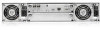
Connecting Switch Attach Configurations This section explains how to connect the controller enclosure to data hosts through one or more external FC switches. The controller enclosure has four host connections, two per controller. Connect FC cables from controller hosts ports to switch ports, and from switch ports to data hosts, as shown in the following figures. To maintain redundancy, connect each data host through the switch or switches to both controller A and controller B. Make sure that link speed and topology settings on switches match those on the controller host ports to which they are connected. A speed mismatch prevents the host from accessing the storage system. Caution - Fiber optic cables are fragile. Do not bend, twist, fold, pinch, or step on the fiber optic cables. Doing so can degrade performance or cause data loss. Note - For clarity, the schematic illustrations of the controllers shown in this section show only relevant details such as host ports. For detailed illustrations showing all components, see "Hardware Components and LEDs" on page 13. Chapter 3 Connecting Hosts 45
-
 1
1 -
2
-
3
-
4
-
5
-
6
-
7
-
8
-
9
-
10
-
11
-
12
-
13
-
14
-
15
-
16
-
17
-
18
-
19
-
20
-
21
-
22
-
23
-
24
-
25
-
26
-
27
-
28
-
29
-
30
-
31
-
32
-
33
-
34
-
35
-
36
-
37
-
38
-
39
-
 40
40 -
 41
41 -
 42
42 -
 43
43 -
 44
44 -
 45
45 -
 46
46 -
 47
47 -
 48
48 -
 49
49 -
 50
50 -
51
-
52
-
53
-
54
-
55
-
56
-
57
-
58
-
59
-
60
-
61
-
62
-
63
-
64
-
65
-
66
-
67
-
68
-
69
-
70
-
71
-
72
-
73
-
74
-
75
-
76
-
77
-
78
-
79
-
80
-
81
-
82
-
83
-
84
-
85
-
86
-
87
-
88
 |
 |
