HP 6400/8400 HP StorageWorks EVA6400/8400 M6412A disk enclosure installation i
HP 6400/8400 Manual
 |
View all HP 6400/8400 manuals
Add to My Manuals
Save this manual to your list of manuals |
HP 6400/8400 manual content summary:
- HP 6400/8400 | HP StorageWorks EVA6400/8400 M6412A disk enclosure installation i - Page 1
HP EVA6400/8400 M6412A disk enclosure installation instructions HP Part Number: 5697-0974 Published: June 2011 Edition: Third - HP 6400/8400 | HP StorageWorks EVA6400/8400 M6412A disk enclosure installation i - Page 2
© Copyright 2009, 2011 Hewlett-Packard Development Company, L.P. - HP 6400/8400 | HP StorageWorks EVA6400/8400 M6412A disk enclosure installation i - Page 3
only add one disk enclosure online at a time. These instructions do not include adding an expansion rack. For expansion rack information, see the HP 6400/8400 Enterprise Virtual Array Expansion Rack Reference Guide. If you print this document, HP recommends that you print it in color, if possible - HP 6400/8400 | HP StorageWorks EVA6400/8400 M6412A disk enclosure installation i - Page 4
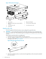
Figure 1 Disk enclosure kit contents 1 Disk enclosure 2 Eight disk drive blanks (may come pre-installed in enclosure) 3 -04 brackets (not used) 4 Accessory kit 5 Rails with -03 brackets 6 Two Fibre Channel copper cables 7 Two enclosure power cords Attaching the rails The rail kit supplied with - HP 6400/8400 | HP StorageWorks EVA6400/8400 M6412A disk enclosure installation i - Page 5
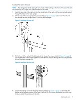
To attach the rails to the rack: NOTE: The designation of left and right rail is made when looking at the front of the rack. The rails are marked by an R (right) and L (left) stamped on the metal. 1. Insert the rear end of the right rail into the inside back of the rack until the pins partially - HP 6400/8400 | HP StorageWorks EVA6400/8400 M6412A disk enclosure installation i - Page 6
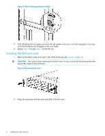
Figure 5 Move retaining bracket to back 5. After attaching the rail, grab and move the rail gently to be sure it is firmly engaged in the rack and that all latches are engaged in the rack holes. 6. Repeat Step 1 through Step 5 for the left rail. Installing the disk enclosure 1. Remove the bezel - HP 6400/8400 | HP StorageWorks EVA6400/8400 M6412A disk enclosure installation i - Page 7
Figure 7 Slide disk enclosure onto rails 3. Continue sliding the enclosure into the rack until the front edge is flush with the front of the rack (1, Figure 8 (page 7)). Tighten the enclosure thumbscrews into the rack (2), taking care not to strip the thumbscrews. Figure 8 Tighten disk enclosure - HP 6400/8400 | HP StorageWorks EVA6400/8400 M6412A disk enclosure installation i - Page 8
6. To install disk drives: a. Insert the disk drive into the drive bay (1, Figure 10 (page 8)) until it clicks, locking the drive. b. Push firmly on the front of the drive carrier to ensure the drive is fully seated into the enclosure. c. Rotate the drive lever to the right (2, Figure 10 (page 8)) - HP 6400/8400 | HP StorageWorks EVA6400/8400 M6412A disk enclosure installation i - Page 9
8400: • One rack may contain two EVA6400 or EVA8400 controllers and a maximum of 18 disk enclosures. The EVA6400 supports a maximum of 18 disk controllers. The EVA8400 supports black power cords on the right side. • The instructions and diagrams in this document reflect the storage-centric racking - HP 6400/8400 | HP StorageWorks EVA6400/8400 M6412A disk enclosure installation i - Page 10
Figure 13 Cabling for an existing EVA6400 2C2D configuration Loop 1 I/O-A P1 / P2 I/O-B P1 / P2 SShheellff--22 ((SS--22)) 01 DP1-MAfg / DP2-A DP1-A DP2-A MP1 FP1 Memory Card FP2 FP3 02 03 04 Controller "A" UID DP1-B / DP2-B FP4 MP2 DP1-B DP2-B PS 1 PS 2 01 MP1 - MP2 - 05 - HP 6400/8400 | HP StorageWorks EVA6400/8400 M6412A disk enclosure installation i - Page 11
11. In HP P6000 Command View, verify that the newly installed disk enclosure appears as part of the array hardware in the navigation pane, and that the I/O modules - HP 6400/8400 | HP StorageWorks EVA6400/8400 M6412A disk enclosure installation i - Page 12
Figure 16 Cabling for an existing EVA8400 2C3D configuration Loop 1 I/O-A P1 / P2 I/O-B P1 / P2 Shelf-3 (S-3) 01 03 02 04 Loop 2 Memory Card DP1-A / DMfPg 2-A / DP3-A DP1-A DP2-A DP3-A MP1 FP1 FP2 FP3 FP4 Controller "A" UID DP1-B / DP2-B / DP3-B MP2 DP1-B DP2-B DP3-B PS 1 PS - HP 6400/8400 | HP StorageWorks EVA6400/8400 M6412A disk enclosure installation i - Page 13
of the next higher enclosure number. For example, if the previous highest index number was "3," then the installed enclosure should display "4." 11. In HP P6000 Command View, verify that the newly installed disk enclosure appears as part of the array hardware in the navigation pane, and that the - HP 6400/8400 | HP StorageWorks EVA6400/8400 M6412A disk enclosure installation i - Page 14
Figure 18 Revised cabling for complete EVA8400 2C4D configuration Loop 1 I/O-A P1 / P2 I/O-B P1 / P2 01 I/O-A P1 / P2 I/O-B P1 / P2 Shelf-4 (S-4) 04 Shelf-3 (S-3) 03 02 Loop 2 Memory Card DP1-AMf/g DP2-A / DP3-A DP1-A DP2-A DP3-A MP1 FP1 FP2 FP3 FP4 Controller "A" UID DP1-B / DP2 - HP 6400/8400 | HP StorageWorks EVA6400/8400 M6412A disk enclosure installation i - Page 15
the newly added enclosure cabled to the array, there will be HP P6000 Command View warnings that indicate disk drives are only connected an extended period of time. Complete the following steps to verify: a. Open HP P6000 Command View. b. Navigate to the newly added disk enclosure within the Hardware
-
 1
1 -
 2
2 -
 3
3 -
 4
4 -
 5
5 -
 6
6 -
 7
7 -
8
-
9
-
10
-
11
-
12
-
13
-
14
-
15
 |
 |

HP EVA6400/8400 M6412A disk enclosure
installation instructions
HP Part Number: 5697-0974
Published: June 2011
Edition: Third