HP 6400/8400 HP StorageWorks EVA6400/8400 M6412A disk enclosure installation i - Page 11
Connecting to an EVA8400 offline
 |
View all HP 6400/8400 manuals
Add to My Manuals
Save this manual to your list of manuals |
Page 11 highlights
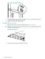
11. In HP P6000 Command View, verify that the newly installed disk enclosure appears as part of the array hardware in the navigation pane, and that the I/O modules show a good operational status. Figure 14 Revised cabling when one disk enclosure is added to loop 1 (EVA6400) Loop 1 I/O-A P1 / P2 I/O-B P1 / P2 Shelf-3 (S-3) 01 04 I/O-A P1 / P2 I/O-B P1 / P2 SShheellff--22 ((SS--22)) 03 DP1-MAfg / DP2-A DP1-A DP2-A MP1 FP1 Memory Card FP2 FP3 UID DP1-B / DP2-B FP4 MP2 DP1-B DP2-B Controller "A" PS 1 PS 2 01 MP1 - MP2 - Jumper Cables 03 Memory Card Controller "B" DP1-AMfg / DP2-A DP1-A DP2-A MP1 FP1 FP2 FP3 UID DP1-B / DP2-B FP4 MP2 DP1-B DP2-B 02 PS 1 PS 2 04 Figure 15 Revised cabling for complete EVA6400 2C3D configuration Loop 1 I/O-A P1 / P2 I/O-B P1 / P2 Shelf-3 (S-3) 01 04 I/O-A P1 / P2 I/O-B P1 / P2 SShheellff--22 ((SS--22)) 03 02 DP1-MAfg / DP2-A DP1-A DP2-A MP1 FP1 Memory Card FP2 FP3 UID DP1-B / DP2-B FP4 MP2 DP1-B DP2-B Controller "A" PS 1 PS 2 01 MP1 - MP2 - 05 Jumper Cables 07 03 Memory Card Controller "B" DP1-AMfg / DP2-A DP1-A DP2-A MP1 FP1 FP2 FP3 UID DP1-B / DP2-B FP4 MP2 DP1-B DP2-B 02 PS 1 PS 2 08 06 04 Loop 2 I/O-A P1 / P2 I/O-B P1 / P2 Shelf-1 (S-1) 05 06 07 08 Connecting to an EVA8400 offline Figure 16 (page 12) shows the cabling for an existing EVA8400 with the controllers between three disk enclosures. Cabling the enclosure 11
-
 1
1 -
2
-
3
-
4
-
5
-
 6
6 -
 7
7 -
 8
8 -
 9
9 -
 10
10 -
 11
11 -
 12
12 -
 13
13 -
 14
14 -
 15
15
 |
 |
