HP A7217A hp 24'' monitor - a7217a, user's guide - Page 5
Identifying parts and controls - usb
 |
UPC - 808736305884
View all HP A7217A manuals
Add to My Manuals
Save this manual to your list of manuals |
Page 5 highlights
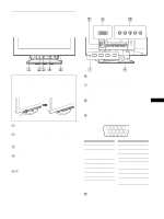
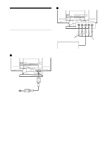
Identifying parts and controls See the pages in parentheses or further details. Front RESET ASC INPUT 1 2 MENU Rear forward side forward side rear side rear side AC IN 1 R G B HD VD 2 To use the control stick This monitor has a cylindrical swivel control stick. To operate the controls, turn the knob on the left side downward to expose the control buttons. When the control buttons are not needed, turn the knob up to hide the control buttons. When not using When using , Knob 1 RESET (reset) button (page 16) This button resets the adjustments to the factory settings. 2 ASC (auto sizing and centering) button (page 9) This button automatically adjusts the size and centering of the picture. 3 INPUT (input) switch (page 9) This switch selects the HD15 or BNC video input signal. 4 Joystick (page 11) The joystick is used to display the menu and make adjustments to the monitor, including brightness and contrast adjustments. 5 ! (power) switch and indicator (pages 7, 16, 20) This button turns the monitor on and off. The power indicator lights up in green when the monitor is turned on, and either flashes in green and orange, or lights up in orange when the monitor is in power saving mode. 6 AC IN connector (page 7) This connector provides AC power to the monitor. 7 USB (universal serial bus) downstream connectors (page 8) Use these connectors to link USB peripheral devices to the monitor. 8 USB (universal serial bus) upstream connector GB (page 8) Use this connector to link the monitor to a USB compliant computer. 9 Video input 1 connector (HD15) (page 6) This connector inputs RGB video signals (0.700 Vp-p, positive) and sync signals. 54321 10 9 8 7 6 15 14 13 12 11 Pin No. Signal 1 Red 2 Green (Composite Sync on Green) 3 Blue 4 ID (Ground) 5 DDC Ground* 6 Red Ground 7 Green Ground Pin No. Signal 8 Blue Ground 9 DDC + 5V* 10 Ground 11 ID (Ground) 12 Bi-Directional Data (SDA)* 13 H. Sync 14 V. Sync 15 Data Clock (SCL)* * DDC (Display Data Channel) is a standard of VESA. q; Video input 2 connector (BNC) (page 6) This connector inputs RGB video signals (0.700 Vp-p, positive) and sync signals. 5
-
 1
1 -
 2
2 -
 3
3 -
 4
4 -
 5
5 -
 6
6 -
 7
7 -
 8
8 -
 9
9 -
 10
10 -
 11
11 -
12
-
13
-
14
-
15
-
16
-
17
-
18
-
19
-
20
-
21
-
22
-
23
-
24
-
25
-
26
-
27
-
28
-
29
-
30
-
31
-
32
-
33
-
34
-
35
-
36
-
37
-
38
-
39
-
40
-
41
-
42
-
43
-
44
-
45
-
46
-
47
-
48
-
49
-
50
-
51
-
52
-
53
-
54
-
55
-
56
-
57
-
58
-
59
-
60
-
61
-
62
-
63
-
64
-
65
-
66
-
67
-
68
-
69
-
70
-
71
-
72
-
73
-
74
-
75
-
76
-
77
-
78
-
79
-
80
-
81
-
82
-
83
-
84
-
85
-
86
-
87
-
88
-
89
-
90
-
91
-
92
-
93
-
94
-
95
-
96
-
97
-
98
-
99
-
100
-
101
-
102
-
103
-
104
-
105
-
106
-
107
-
108
-
109
-
110
-
111
-
112
-
113
-
114
-
115
-
116
-
117
-
118
-
119
-
120
-
121
-
122
-
123
-
124
-
125
-
126
-
127
-
128
-
129
-
130
-
131
-
132
 |
 |
