HP BL260c ISS Technology Update, Volume 6 Number 7 - Newsletter - Page 13
Additional resources, Cabling stacked HP 1/10G Virtual Connect Ethernet Modules, ISS Technology Update
 |
UPC - 883585668663
View all HP BL260c manuals
Add to My Manuals
Save this manual to your list of manuals |
Page 13 highlights
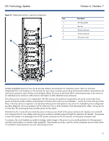
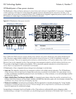
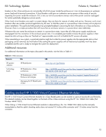
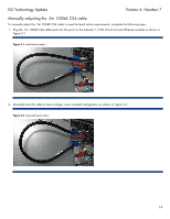
ISS Technology Update Volume 6, Number 7 breaker on the c-Class enclosure can not possibly kill all AC power inside the enclosure as it can not de-energize an upstream power lead and its terminal connections. A local breaker could give an inattentive service person a false sense of security regarding live power inside the enclosure. This is why our service procedures always instruct that power cords be unplugged for certain potentially dangerous service events. When local circuit breakers are used in a system design, they are there for reasons of safety and service. However, such circuit breakers often see another practical application by the user: to hold the system in a power-down state at times such as physical system installation. This particular field practice has prompted feedback concerning the lack of breakers on c-Class enclosures. However, there is a simple procedure that will insure that an enclosure remains in a power-down state indefinitely. Whenever the user wants the enclosure to remain in a power-down state, insure that all of the power supply modules are disengaged from the connectors in the enclosure power slots. It is completely permissible to leave the power supplies in their respective slots as long as they are "backed out" approximately one inch to disable the DC power sub-system. When assembling a new system, a practical practice might be to slide the power supplies into the appropriate slots so that packaging can be removed, but wait before fully seating the power supplies until all mechanical assembly work has been completed and the user is ready to energize the system for deployment. Additional resources For additional information on the topics discussed in this article, visit the links in Table 4-1. Table 4-1. Web resources Resource Title URL HP product websites Technology briefs HP BladeSystem www.hp.com/go/blades HP BladeSystem c-Class architecture HP BladeSystem c7000 Enclosure technologies Managing the HP BladeSystem c-Class http://h20000.www2.hp.com/bc/docs/support/SupportManual/c0 0810839/c00810839.pdf http://h20000.www2.hp.com/bc/docs/support/SupportManual/c0 0816246/c00816246.pdf http://h20000.www2.hp.com/bc/docs/support/SupportManual/c0 0814176/c00814176.pdf Cabling stacked HP 1/10G Virtual Connect Ethernet Modules The HP 1/10G Virtual Connect Ethernet Modules for c-Class BladeSystem can be stacked to optimize bandwidth and flexibility. The stacked modules can be linked together on the back of the c-Class enclosure using the HP .5m 10GbE CX4 Cable (Part Number 444477-B21). When linking 1/10G Virtual Connect Ethernet modules in adjacent bays, the .5m 10GbE CX4 cable must be manually manipulated so that the cable's bending radius does not exceed 4.0 inches at the connector and 1.5 inches away from the connector. 13
-
 1
1 -
2
-
3
-
4
-
5
-
6
-
7
-
 8
8 -
 9
9 -
 10
10 -
 11
11 -
 12
12 -
 13
13 -
 14
14 -
 15
15 -
 16
16 -
 17
17 -
 18
18 -
19
-
20
 |
 |
