HP Classmate Notebook PC Classmate Notebook Maintenance and Service Guide
HP Classmate Notebook PC Manual
 |
View all HP Classmate Notebook PC manuals
Add to My Manuals
Save this manual to your list of manuals |
HP Classmate Notebook PC manual content summary:
- HP Classmate Notebook PC | Classmate Notebook Maintenance and Service Guide - Page 1
HP Classmate Notebook Maintenance and Service Guide IMPORTANT! This document is intended for HP authorized service providers only. - HP Classmate Notebook PC | Classmate Notebook Maintenance and Service Guide - Page 2
such products and services. Nothing herein should be construed as constituting an additional warranty. HP shall not be liable for technical or editorial errors or omissions contained herein. First Edition: June 2014 Document Part Number: 760165-001 Product notice This guide describes features that - HP Classmate Notebook PC | Classmate Notebook Maintenance and Service Guide - Page 3
Safety warning notice WARNING! To reduce the possibility of heat-related injuries or of overheating the computer, do not place the computer directly on your lap or obstruct the computer air vents. Use the computer only on a hard, flat surface. Do not allow another hard surface, such as an adjoining - HP Classmate Notebook PC | Classmate Notebook Maintenance and Service Guide - Page 4
iv Safety warning notice - HP Classmate Notebook PC | Classmate Notebook Maintenance and Service Guide - Page 5
damage 19 Packaging and transporting guidelines 20 Workstation guidelines 20 Equipment guidelines 21 5 Removal and replacement procedures for Authorized Service Provider parts 22 Component replacement procedures ...22 Bottom cover ...22 Memory module ...24 WLAN/Bluetooth combo card ...26 - HP Classmate Notebook PC | Classmate Notebook Maintenance and Service Guide - Page 6
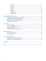
Heat sink ...33 Power cable ...35 Hard drive ...37 Battery ...40 I/O board ...41 System board ...42 RTC battery ...44 Display assembly ...46 6 Backing up, restoring, and recovering ...55 Creating a Microsoft recovery drive (select models only 55 Using Windows Refresh for quick and easy recovery 56 - HP Classmate Notebook PC | Classmate Notebook Maintenance and Service Guide - Page 7
-VL 10/100 Ethernet Integrated WLAN by way of wireless module: LiteOn/AzureWave 802.11 b/g/n 1x1 + BT 4.0 combo Digital Media Reader Slot Supports SDHC Headphone/Microphone/Thermal probe combo jack RJ-45 (Ethernet) USB 3.0 (1) USB 2.0 (1) HDMI DC-in jack Integrated QWERTY keyboard with hot key - HP Classmate Notebook PC | Classmate Notebook Maintenance and Service Guide - Page 8
Category Security Operating system Serviceability Description 3-cell, 34-Wh, 3.4 Ah, polymer battery Security lock TPM drivers only) NOTE: Portable optical drive required to use restore media. Web-only support: Windows 8.1 Professional 64 Windows 8.1 Enterprise 64 Certified: Microsoft WHQL End-user - HP Classmate Notebook PC | Classmate Notebook Maintenance and Service Guide - Page 9
2 External component identification Front Component (1) (2) (3) Internal microphone Webcam Power button Description Record sound. Records video and captures photographs. ● When the computer is off, press the button to turn on the computer. ● When the computer is on, press the button briefly to - HP Classmate Notebook PC | Classmate Notebook Maintenance and Service Guide - Page 10
. For wireless regulatory notices, see the section of the Regulatory, Safety, and Environmental Notices that applies to your country or region. To access this guide, from the Start screen, type support, and then select the HP Support Assistant app. 4 Chapter 2 External component identification - HP Classmate Notebook PC | Classmate Notebook Maintenance and Service Guide - Page 11
Left Component (13) Security cable slot (14) USB 3.0 port, identifying (15) HDMI port (16) Memory card reader Description Attaches an optional security cable to the computer. NOTE: The security cable is designed to act as a deterrent, but it may not prevent the computer from being - HP Classmate Notebook PC | Classmate Notebook Maintenance and Service Guide - Page 12
a headset. For additional safety information, see the Regulatory, Safety, and Environmental Notices. To access this guide, from the Start screen, type support, and then select the HP Support Assistant app. NOTE: When a device is connected to the jack, the computer speakers are disabled. 6 Chapter - HP Classmate Notebook PC | Classmate Notebook Maintenance and Service Guide - Page 13
Rear Component (19) (20) Power connector RJ-45 (network) jack/lights Description Connects an AC adapter. Connects a network cable. ● Green (right): The network is connected. ● Amber (left): Activity is occurring on the network. Rear 7 - HP Classmate Notebook PC | Classmate Notebook Maintenance and Service Guide - Page 14
tag When ordering parts or requesting information, provide the computer serial number and model description provided on the service tag. ● Serial (1). This is an alphanumeric identifier that is unique to each product. ● Product name (2). This is the product name affixed to the front of - HP Classmate Notebook PC | Classmate Notebook Maintenance and Service Guide - Page 15
current information on supported parts for your computer, go to http://partsurfer.hp.com, select your country or region, and then follow the on-screen instructions. NOTE: Details about your computer, including model, serial number, product key, and length of warranty, are on the service tag at the - HP Classmate Notebook PC | Classmate Notebook Maintenance and Service Guide - Page 16
Item (1) (2) Description Whole unit replacement Latin America The United Kingdom The United States Top cover (includes touchpad and handle kit) Keyboard (includes cable) 10 Chapter 3 Illustrated parts catalog Spare part number 762412-001 762411-001 762410-001 764406-001 - HP Classmate Notebook PC | Classmate Notebook Maintenance and Service Guide - Page 17
Item (3) (4) (5) (6) (7) (8) (9) (10) (11) (12) Description For use in the United States For use in Latin America System board with Celeron N2806 processor (includes replacement thermal material) I/O board Heat sink (includes replacement thermal material) Battery 3-cell, 34-Wh, 3.4 Ah, polymer - HP Classmate Notebook PC | Classmate Notebook Maintenance and Service Guide - Page 18
Display components Item (1) (2) (3) (4) (5) (6) (7) Description Display panel (raw) Display bezel Display Hinge Kit (includes left and right hinges) Webcam module Display hinge cover Display rear cover Display panel frame Spare part number 778821-001 778822-001 764405-001 778819-001 764416-001 - HP Classmate Notebook PC | Classmate Notebook Maintenance and Service Guide - Page 19
Cable Kit Item (1) (2) (3) Description Cable Kit Touchpad cable Narrow flat ribbon cable Wide flat ribbon cable Spare part number 764412-001 Cable Kit 13 - HP Classmate Notebook PC | Classmate Notebook Maintenance and Service Guide - Page 20
Hard drive components Description (1) Hard drives 320-GB, 5400-rpm, 7 mm Hard Drive Hardware Kit, includes: (2) Hard drive bracket (3) Rubber rails Sponge (not illustrated) Screws (not illustrated) (4) Hard drive connector cable 14 Chapter 3 Illustrated parts catalog Spare part number - HP Classmate Notebook PC | Classmate Notebook Maintenance and Service Guide - Page 21
Miscellaneous parts Description AC adapter, 40-W Power cord Rubber Kit (includes all rubber covers and pads) Screw Kit Spare part number 778816-001 778815-001 764417-001 780744-001 Sequential part number listing Spare part number 691739-005 762410-001 762411-001 762412-001 764403-001 764405-001 - HP Classmate Notebook PC | Classmate Notebook Maintenance and Service Guide - Page 22
Spare part number 778823-001 778823-161 778821-001 780744-001 786030-001 786031-001 788292-001 Description Keyboard for use in the United States Keyboard for use in Latin America Display panel (raw) Screw Kit 320-GB, 5400-rpm, 7 mm, hard drive 3-cell, 37 WHr, 3.4 Ah Li-ion battery 802.11b/g/n 1x1 - HP Classmate Notebook PC | Classmate Notebook Maintenance and Service Guide - Page 23
● Flat-bladed screwdriver ● Phillips P0 and P1 screwdrivers ● Torx T8 screwdriver Service considerations The following sections include some of the considerations that you must keep in mind plastic parts. Apply pressure only at the points designated in the maintenance instructions. Tools required 17 - HP Classmate Notebook PC | Classmate Notebook Maintenance and Service Guide - Page 24
Cables and connectors CAUTION: When servicing the computer, be sure that cables are placed in their proper locations during the reassembly process. Improper cable placement can damage the computer. Cables must - HP Classmate Notebook PC | Classmate Notebook Maintenance and Service Guide - Page 25
V 2,000 V 700 V 11,500 V 4,000 V 14,500 V 5,000 V 26,500 V 20,000 V 21,000 V 11,000 V 55% 7,500 V 3,000 V 400 V 400 V 2,000 V 3,500 V 7,000 V 5,000 V Service considerations 19 - HP Classmate Notebook PC | Classmate Notebook Maintenance and Service Guide - Page 26
material. ● Use a wrist strap connected to a properly grounded work surface and use properly grounded tools and equipment. ● Use conductive field service tools, such as cutters, screwdrivers, and vacuums. ● When fixtures must directly contact dissipative surfaces, use fixtures made only of static - HP Classmate Notebook PC | Classmate Notebook Maintenance and Service Guide - Page 27
with ground cords of one megohm resistance ● Static-dissipative tables or floor mats with hard ties to the ground ● Field service kits ● Static awareness labels ● Material-handling packages ● Nonconductive plastic bags, tubes, or boxes ● Metal tote boxes ● Electrostatic voltage levels and - HP Classmate Notebook PC | Classmate Notebook Maintenance and Service Guide - Page 28
current information on supported parts for your computer, go to http://partsurfer.hp.com, select your country or region, and then follow the on-screen instructions. NOTE: Details about your computer, including model, serial number, product key, and length of warranty, are on the service tag at the - HP Classmate Notebook PC | Classmate Notebook Maintenance and Service Guide - Page 29
2. Remove the 8 rubber screw covers from atop the screws. The screw covers are different sizes based on location, so be sure to make note of each screw covers location for replacement. 3. Remove the 2 Phillips M2.5×8.0 screws and 6 Phillips M2.5×6.0 screws that secure the bottom cover to the - HP Classmate Notebook PC | Classmate Notebook Maintenance and Service Guide - Page 30
memory may result in various system problems. To update BIOS: 1. Navigate to www.hp.com. 2. Click Support & Drivers > click Drivers & . 8. Click the Download button, and then follow the on-screen instructions. Before removing the memory module, follow these steps: 1. Shut down Service Provider parts - HP Classmate Notebook PC | Classmate Notebook Maintenance and Service Guide - Page 31
Remove the memory module: 1. Spread the retaining tabs (1) on each side of the memory module slot to release the memory module. (The edge of the module opposite the slot rises away from the computer.) 2. Remove the memory module (2) by pulling the module away from the slot at an angle. NOTE: Memory - HP Classmate Notebook PC | Classmate Notebook Maintenance and Service Guide - Page 32
module "Aux" terminal labeled "2". 2. Remove the Phillips PM2.0×4.0 screw (2) that secures the WLAN module to the computer. 26 Chapter 5 Removal and replacement procedures for Authorized Service Provider parts - HP Classmate Notebook PC | Classmate Notebook Maintenance and Service Guide - Page 33
3. Remove the WLAN module (3) by pulling the module away from the slot. NOTE: WLAN modules are designed with a notch to prevent incorrect insertion. NOTE: If the WLAN antennas are not connected to the terminals on the WLAN module, the protective sleeves must be installed on the antenna connectors, - HP Classmate Notebook PC | Classmate Notebook Maintenance and Service Guide - Page 34
, press the 4 latches (1) at the top of the keyboard upward to disengage the keyboard from the computer. 28 Chapter 5 Removal and replacement procedures for Authorized Service Provider parts - HP Classmate Notebook PC | Classmate Notebook Maintenance and Service Guide - Page 35
3. Lift the top of the keyboard upward (2), and place the keyboard on the palm rest. 4. Disconnect the keyboard cable from the system board. Component replacement procedures 29 - HP Classmate Notebook PC | Classmate Notebook Maintenance and Service Guide - Page 36
the touchpad cable if you need remove the system board. Reverse this procedure to install the keyboard. 30 Chapter 5 Removal and replacement procedures for Authorized Service Provider parts - HP Classmate Notebook PC | Classmate Notebook Maintenance and Service Guide - Page 37
Speaker assembly Description Speaker assembly Spare part number 764411-001 Before removing the speaker assembly, follow these steps: 1. Shut down the computer. If you are unsure whether the computer is off or in Hibernation, turn the computer on, and then shut it down through the operating system. - HP Classmate Notebook PC | Classmate Notebook Maintenance and Service Guide - Page 38
3. Lift the pieces of tape that secure the speaker cable to the computer (3), and then remove the speakers. Reverse this procedure to install the speaker assembly. 32 Chapter 5 Removal and replacement procedures for Authorized Service Provider parts - HP Classmate Notebook PC | Classmate Notebook Maintenance and Service Guide - Page 39
Heat sink All heat sink spare part kits include replacement thermal material. Description Heat sink Spare part number 764414-001 Before removing the heat sink assembly, follow these steps: 1. Shut down the computer. If you are unsure whether the computer is off or in Hibernation, turn the computer - HP Classmate Notebook PC | Classmate Notebook Maintenance and Service Guide - Page 40
and processor spare part kits include thermal material. Reverse this procedure to install the heat sink assembly. 34 Chapter 5 Removal and replacement procedures for Authorized Service Provider parts - HP Classmate Notebook PC | Classmate Notebook Maintenance and Service Guide - Page 41
Power cable Description Power cable Spare part number 764410-001 Before removing the power cable, follow these steps: 1. Shut down the computer. If you are unsure whether the computer is off or in Hibernation, turn the computer on, and then shut it down through the operating system. 2. Disconnect - HP Classmate Notebook PC | Classmate Notebook Maintenance and Service Guide - Page 42
3. Lift the power cable from the computer (4). Reverse this procedure to install the power cable. 36 Chapter 5 Removal and replacement procedures for Authorized Service Provider parts - HP Classmate Notebook PC | Classmate Notebook Maintenance and Service Guide - Page 43
Hard drive Description 320-GB, 5400-rpm, 7 mm hard drive Hard Drive Hardware Kit (includes hard drive bracket, rubber rails, sponge, and screws) Hard drive connector cable Spare part number 786030-001 764408-001 764409-001 Before removing the hard drive, follow these steps: 1. Shut down the - HP Classmate Notebook PC | Classmate Notebook Maintenance and Service Guide - Page 44
disconnect it from the drive (3). NOTE: You must remove the bracket before you can remove the cable. 38 Chapter 5 Removal and replacement procedures for Authorized Service Provider parts - HP Classmate Notebook PC | Classmate Notebook Maintenance and Service Guide - Page 45
7. To remove the rubber rails from the hard drive, pull each rail off to disengage the adhesive that secures the rail to the drive. Reverse this procedure to install a hard drive. Component replacement procedures 39 - HP Classmate Notebook PC | Classmate Notebook Maintenance and Service Guide - Page 46
the system board connector (2). 3. Remove the battery from the computer (3). Reverse this procedure to install the battery. 40 Chapter 5 Removal and replacement procedures for Authorized Service Provider parts - HP Classmate Notebook PC | Classmate Notebook Maintenance and Service Guide - Page 47
I/O board Description I/O board Spare part number 764413-001 Before removing the I/O board, follow these steps: 1. Shut down the computer. If you are unsure whether the computer is off or in Hibernation, turn the computer on, and then shut it down through the operating system. 2. Disconnect all - HP Classmate Notebook PC | Classmate Notebook Maintenance and Service Guide - Page 48
ribbon cable (after removing tape on top) (4): Hard drive cable (after removing tape on top) (5): Display cable 42 Chapter 5 Removal and replacement procedures for Authorized Service Provider parts - HP Classmate Notebook PC | Classmate Notebook Maintenance and Service Guide - Page 49
2. Remove the 3 nuts (1) and 2 Phillips PM2.0×5.5 screws (2) that secure the system board to the computer. 3. Pull the system board away from the side of the computer to release the connectors, and then remove it from the computer. Reverse this procedure to install the system board. Component - HP Classmate Notebook PC | Classmate Notebook Maintenance and Service Guide - Page 50
from the system board connector (1). 3. Lift the Mylar tape that secures the cable to the system board (2). 44 Chapter 5 Removal and replacement procedures for Authorized Service Provider parts - HP Classmate Notebook PC | Classmate Notebook Maintenance and Service Guide - Page 51
4. Lift the battery to disengage it from the adhesive that secures it to the system board (3). Reverse this procedure to install the RTC battery. Component replacement procedures 45 - HP Classmate Notebook PC | Classmate Notebook Maintenance and Service Guide - Page 52
webcam (2): 2 rubber screw covers near the hinge cover (3): 4 round rubber bumpers in the corners of the display 46 Chapter 5 Removal and replacement procedures for Authorized Service Provider parts - HP Classmate Notebook PC | Classmate Notebook Maintenance and Service Guide - Page 53
2. Remove the 2 Phillips PM2.5×5.0 screws (1) and the 6 Phillips PM2.5×4.0 screws (2) that secure the display rear cover to the display bezel. Component replacement procedures 47 - HP Classmate Notebook PC | Classmate Notebook Maintenance and Service Guide - Page 54
connected webcam aside. 5. Lift the tape that secures the wireless transceivers to the sides of the display (3). 48 Chapter 5 Removal and replacement procedures for Authorized Service Provider parts - HP Classmate Notebook PC | Classmate Notebook Maintenance and Service Guide - Page 55
6. Lift the various pieces of tape that secure the display panel to the display (4). 7. Remove the 4 Phillips PM2.5×4.0 screws (1) that secure the display panel to the bezel. 8. Lift the tape over the display panel connector (2) and disconnect the cable from the panel (3). Component replacement - HP Classmate Notebook PC | Classmate Notebook Maintenance and Service Guide - Page 56
spare part number 778821-001. The display panel frame is available using spare part number 778820-001. 50 Chapter 5 Removal and replacement procedures for Authorized Service Provider parts - HP Classmate Notebook PC | Classmate Notebook Maintenance and Service Guide - Page 57
11. Removing the remaining components requires removing the display assembly from the computer. To remove the display assembly, first remove the display hinge cover by prying the cover off with a thin tool. The display hinge cover is available using spare part number 764416-001. 12. To remove the - HP Classmate Notebook PC | Classmate Notebook Maintenance and Service Guide - Page 58
display panel from the bezel (see step 8), and then remove the antennas from the bezel as follows: 52 Chapter 5 Removal and replacement procedures for Authorized Service Provider parts - HP Classmate Notebook PC | Classmate Notebook Maintenance and Service Guide - Page 59
a. Lift the tape that secures the transceivers to the sides of the bezel (1). b. Remove the cables from the routing channels built into the bezel (2). c. Lift the tape that secures the antennas to the bezel (3). The bezel is available using spare part number 778822-001. CAUTION: When installing the - HP Classmate Notebook PC | Classmate Notebook Maintenance and Service Guide - Page 60
Kit using spare part number 764405-001. Reverse this procedure to reassemble and install the display assembly. 54 Chapter 5 Removal and replacement procedures for Authorized Service Provider parts - HP Classmate Notebook PC | Classmate Notebook Maintenance and Service Guide - Page 61
provided, see Help and Support. From the Start screen, type help, and then select Help and Support. Creating a Microsoft recovery drive recovery drive is selected. 2. Select Next, and then follow the on-screen instructions. 3. After you have created the recovery drive, a prompt is displayed asking - HP Classmate Notebook PC | Classmate Notebook Maintenance and Service Guide - Page 62
you have a quick way to see what you might need to reinstall. See Help and Support for instructions on reinstalling traditional applications. From the Start screen, type help, and then select Help and Support. NOTE: You may be prompted for your permission or password when using Refresh. See Help - HP Classmate Notebook PC | Classmate Notebook Maintenance and Service Guide - Page 63
7 Specifications Computer specifications Dimensions Length Depth Height (front to rear) Weight SATA flash/webcam/2cell battery Input power Input Output DC output Temperature Operating Nonoperating Relative humidity Operating Nonoperating Maximum altitude (unpressurized) Operating (14.7 to 10.1 psia) - HP Classmate Notebook PC | Classmate Notebook Maintenance and Service Guide - Page 64
25.7-cm (10.1-in) display specifications Active diagonal size Resolution Active area PPI Surface treatment Contrast ratio Refresh rate Brightness Viewing angle Backlight Pixel resolution Pitch Format Configuration Metric U.S. 256.5 mm 10.1-cm 1280x800 8.75x4.91 in (222.22.x124.81 mm) 150 - HP Classmate Notebook PC | Classmate Notebook Maintenance and Service Guide - Page 65
. Actual accessible capacity is less. Actual drive specifications may differ slightly. NOTE: Certain restrictions and exclusions apply. Contact technical support for details. Specification information in Device Manager Device Manager allows you to view and control the hardware attached to the - HP Classmate Notebook PC | Classmate Notebook Maintenance and Service Guide - Page 66
based HP Business Notebook PC systems and provide general instructions for restoring nonvolatile memory that can contain personal data these steps are disclosed in the Maintenance & Service Guides available for HP PC products available on the product support pages at www.hp.com. 1. Follow - HP Classmate Notebook PC | Classmate Notebook Maintenance and Service Guide - Page 67
Intel® Anti-Theft Technology (AT) was activated, contact the provider to deactivate it. k. If the optional Absolute® Software Computrace® management and tracking service was activated on the notebook PC, contact the provider to deactivate it. l. Remove all power and system batteries for at least 24 - HP Classmate Notebook PC | Classmate Notebook Maintenance and Service Guide - Page 68
Non-volatile memory usage Non Volatile Memory Type Amount (Size) Real Time Clock (RTC) battery backed-up CMOS configuration memory (CMOS) 256 Bytes Controller (NIC) EEPROM 64 Kbytes (not customer accessible) Does this memory store customer data? No No Keyboard ROM 64 Kbytes No (not customer - HP Classmate Notebook PC | Classmate Notebook Maintenance and Service Guide - Page 69
Bluetooth flash 2Mbit No Yes 802.11 WLAN 4kb to 8kb No Yes EEPROM Web camera 64K bit No Yes Fingerprint 512kByte Yes Yes reader Flash third party data store contents can populated by a remote management console or local applications registered by an administrator to have access to the - HP Classmate Notebook PC | Classmate Notebook Maintenance and Service Guide - Page 70
the computer and press F10 when prompted near the bottom of the display. b. Select File, then select Restore defaults. c. Follow the on-screen instructions. d. Select File, save changes and exit, then press Enter. 2. What kind of configuration data is stored on the DIMM Serial Presence Detect (SPD - HP Classmate Notebook PC | Classmate Notebook Maintenance and Service Guide - Page 71
9 Power cord set requirements The wide-range input feature of the computer permits it to operate from any line voltage from 100 to 120 volts ac, or from 220 to 240 volts ac. The 3-conductor power cord set included with the computer meets the requirements for use in the country or region where the - HP Classmate Notebook PC | Classmate Notebook Maintenance and Service Guide - Page 72
Country/region Accredited agency Applicable note number Japan JIS 3 The Netherlands KEMA 1 New Zealand SANZ 1 Norway NEMKO 1 The People's Republic of China CCC 4 Saudi Arabia SASO 7 Singapore PSB 1 South Africa SABS 1 South Korea KTL 5 Sweden SEMKO 1 Switzerland SEV - HP Classmate Notebook PC | Classmate Notebook Maintenance and Service Guide - Page 73
10 Recycling When a non-rechargeable or rechargeable battery has reached the end of its useful life, do not dispose of the battery in general household waste. Follow the local laws and regulations in your area for battery disposal. HP encourages customers to recycle used electronic hardware, HP - HP Classmate Notebook PC | Classmate Notebook Maintenance and Service Guide - Page 74
, illustrated 13 Bluetooth card spare part number 26 bottom cover removal 22 spare part number 22 C Cable Kit contents 13 spare part number 13 cables, service considerations 18 chipset, product description 1 components front 3 left side 5 rear 7 right side 6 computer specifications 57 connectors - HP Classmate Notebook PC | Classmate Notebook Maintenance and Service Guide - Page 75
number 11, 15, 44 S Screw Kit, spare part number 15 security cable slot, identifying 5 security, product description 2 service considerations 17 service tag 8 serviceability, product description 2 slots security cable 5 speaker assembly removal 31 spare part number 11, 31 specifications computer 57
-
 1
1 -
 2
2 -
 3
3 -
 4
4 -
 5
5 -
 6
6 -
 7
7 -
8
-
9
-
10
-
11
-
12
-
13
-
14
-
15
-
16
-
17
-
18
-
19
-
20
-
21
-
22
-
23
-
24
-
25
-
26
-
27
-
28
-
29
-
30
-
31
-
32
-
33
-
34
-
35
-
36
-
37
-
38
-
39
-
40
-
41
-
42
-
43
-
44
-
45
-
46
-
47
-
48
-
49
-
50
-
51
-
52
-
53
-
54
-
55
-
56
-
57
-
58
-
59
-
60
-
61
-
62
-
63
-
64
-
65
-
66
-
67
-
68
-
69
-
70
-
71
-
72
-
73
-
74
-
75
 |
 |

HP Classmate Notebook
Maintenance and Service Guide
IMPORTANT! This document is intended for HP
authorized service providers only.