HP Dv4-1124nr HP Pavilion dv4 Entertainment PC - Maintenance and Service Guide - Page 130
Lift the processor, one-half turn counterclockwise until you hear a click.
 |
UPC - 884420609841
View all HP Dv4-1124nr manuals
Add to My Manuals
Save this manual to your list of manuals |
Page 130 highlights
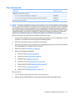
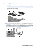
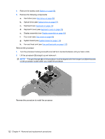
4. Remove the battery (see Battery on page 55). 5. Remove the following components: a. Hard drive (see Hard drive on page 59) b. Optical drive (see Optical drive on page 57) c. Keyboard (see Keyboard on page 72) d. Keyboard cover (see Keyboard cover on page 76) e. Display assembly (see Display assembly on page 83) f. Top cover (see Top cover on page 95) g. System board (see System board on page 110) h. Fan and heat sink (see Fan and heat sink on page 117) Remove the processor: 1. Turn the processor locking screw (1) one-half turn counterclockwise until you hear a click. 2. Lift the processor (2) straight up and remove it. NOTE: The gold triangle (3) on the processor must be aligned with the triangle icon (4) embossed on the processor socket when you install the processor. Reverse this procedure to install the processor. 122 Chapter 4 Removal and replacement procedures
-
 1
1 -
2
-
3
-
4
-
5
-
6
-
7
-
8
-
9
-
10
-
11
-
12
-
13
-
14
-
15
-
16
-
17
-
18
-
19
-
20
-
21
-
22
-
23
-
24
-
25
-
26
-
27
-
28
-
29
-
30
-
31
-
32
-
33
-
34
-
35
-
36
-
37
-
38
-
39
-
40
-
41
-
42
-
43
-
44
-
45
-
46
-
47
-
48
-
49
-
50
-
51
-
52
-
53
-
54
-
55
-
56
-
57
-
58
-
59
-
60
-
61
-
62
-
63
-
64
-
65
-
66
-
67
-
68
-
69
-
70
-
71
-
72
-
73
-
74
-
75
-
76
-
77
-
78
-
79
-
80
-
81
-
82
-
83
-
84
-
85
-
86
-
87
-
88
-
89
-
90
-
91
-
92
-
93
-
94
-
95
-
96
-
97
-
98
-
99
-
100
-
101
-
102
-
103
-
104
-
105
-
106
-
107
-
108
-
109
-
110
-
111
-
112
-
113
-
114
-
115
-
116
-
117
-
118
-
119
-
120
-
121
-
122
-
123
-
124
-
 125
125 -
 126
126 -
 127
127 -
 128
128 -
 129
129 -
 130
130 -
 131
131 -
 132
132 -
 133
133 -
 134
134 -
 135
135 -
136
-
137
-
138
-
139
-
140
-
141
-
142
-
143
-
144
-
145
-
146
-
147
-
148
-
149
-
150
-
151
-
152
-
153
-
154
-
155
-
156
-
157
-
158
-
159
-
160
-
161
-
162
-
163
-
164
-
165
-
166
-
167
-
168
-
169
-
170
-
171
-
172
-
173
-
174
-
175
-
176
-
177
-
178
-
179
-
180
-
181
-
182
-
183
-
184
-
185
-
186
-
187
-
188
-
189
-
190
-
191
-
192
-
193
-
194
-
195
-
196
-
197
-
198
-
199
-
200
-
201
-
202
 |
 |
