HP Dv4-1124nr HP Pavilion dv4 Entertainment PC - Maintenance and Service Guide - Page 72
Remove the 2 Phillips PM2.0×4.0 screws, WLAN modules are designed with a notch
 |
UPC - 884420609841
View all HP Dv4-1124nr manuals
Add to My Manuals
Save this manual to your list of manuals |
Page 72 highlights
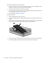
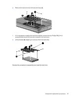
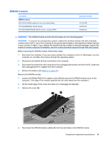
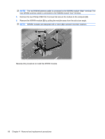
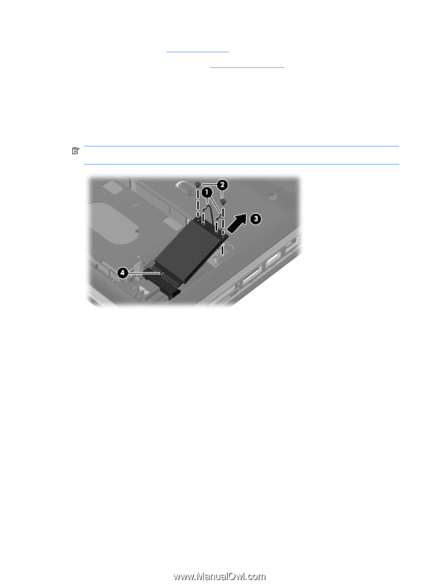
4. Remove the battery (see Battery on page 55). 5. Remove the hard drive bay cover (see Hard drive on page 59) Remove the WLAN module: 1. Disconnect the wireless antenna wires (1) from the from the wireless module. 2. Remove the 2 Phillips PM2.0×4.0 screws (2) securing the WLAN module to the computer. 3. Remove the WLAN module (3) by pulling it away from the slot at an angle. (The edge of the module opposite the slot rises away from the computer.) NOTE: WLAN modules are designed with a notch (4) to prevent incorrect insertion into the WLAN module slot. Reverse this procedure to install a WLAN module. 64 Chapter 4 Removal and replacement procedures
-
 1
1 -
2
-
3
-
4
-
5
-
6
-
7
-
8
-
9
-
10
-
11
-
12
-
13
-
14
-
15
-
16
-
17
-
18
-
19
-
20
-
21
-
22
-
23
-
24
-
25
-
26
-
27
-
28
-
29
-
30
-
31
-
32
-
33
-
34
-
35
-
36
-
37
-
38
-
39
-
40
-
41
-
42
-
43
-
44
-
45
-
46
-
47
-
48
-
49
-
50
-
51
-
52
-
53
-
54
-
55
-
56
-
57
-
58
-
59
-
60
-
61
-
62
-
63
-
64
-
65
-
66
-
 67
67 -
 68
68 -
 69
69 -
 70
70 -
 71
71 -
 72
72 -
 73
73 -
 74
74 -
 75
75 -
 76
76 -
 77
77 -
78
-
79
-
80
-
81
-
82
-
83
-
84
-
85
-
86
-
87
-
88
-
89
-
90
-
91
-
92
-
93
-
94
-
95
-
96
-
97
-
98
-
99
-
100
-
101
-
102
-
103
-
104
-
105
-
106
-
107
-
108
-
109
-
110
-
111
-
112
-
113
-
114
-
115
-
116
-
117
-
118
-
119
-
120
-
121
-
122
-
123
-
124
-
125
-
126
-
127
-
128
-
129
-
130
-
131
-
132
-
133
-
134
-
135
-
136
-
137
-
138
-
139
-
140
-
141
-
142
-
143
-
144
-
145
-
146
-
147
-
148
-
149
-
150
-
151
-
152
-
153
-
154
-
155
-
156
-
157
-
158
-
159
-
160
-
161
-
162
-
163
-
164
-
165
-
166
-
167
-
168
-
169
-
170
-
171
-
172
-
173
-
174
-
175
-
176
-
177
-
178
-
179
-
180
-
181
-
182
-
183
-
184
-
185
-
186
-
187
-
188
-
189
-
190
-
191
-
192
-
193
-
194
-
195
-
196
-
197
-
198
-
199
-
200
-
201
-
202
 |
 |
4.
Remove the battery (see
Battery
on page
55
).
5.
Remove the hard drive bay cover (see
Hard drive
on page
59
)
Remove the WLAN module:
1.
Disconnect the wireless antenna wires
(1)
from the from the wireless module.
2.
Remove the 2 Phillips PM2.0×4.0 screws
(2)
securing the WLAN module to the computer.
3.
Remove the WLAN module
(3)
by pulling it away from the slot at an angle. (The edge of the module
opposite the slot rises away from the computer.)
NOTE:
WLAN modules are designed with a notch
(4)
to prevent incorrect insertion into the WLAN
module slot.
Reverse this procedure to install a WLAN module.
64
Chapter 4
Removal and replacement procedures