HP Dv4-1124nr HP Pavilion dv4 Entertainment PC - Maintenance and Service Guide - Page 97
built into the display enclosure., Remove the wireless antenna cables from the clips
 |
UPC - 884420609841
View all HP Dv4-1124nr manuals
Add to My Manuals
Save this manual to your list of manuals |
Page 97 highlights
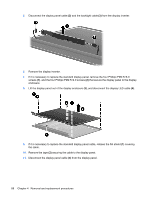
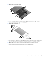
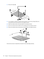
12. Remove the display panel cable (4). 13. If it is necessary to replace the standard display hinges, remove the eight Phillips PM2.0×4.0 screws (1) that secure the hinges to the display panel. 14. Remove the display hinges (2). 15. If it is necessary to replace the standard display wireless antenna transceivers and cables, remove the two Phillips PM2.5×4.0 screws (1) that secure each transceiver to the display enclosure. 16. Remove the wireless antenna cables from the clips (2) built into the display enclosure. 17. Detach the wireless antenna transceivers (3) from the display enclosure. Component replacement procedures 89
-
 1
1 -
2
-
3
-
4
-
5
-
6
-
7
-
8
-
9
-
10
-
11
-
12
-
13
-
14
-
15
-
16
-
17
-
18
-
19
-
20
-
21
-
22
-
23
-
24
-
25
-
26
-
27
-
28
-
29
-
30
-
31
-
32
-
33
-
34
-
35
-
36
-
37
-
38
-
39
-
40
-
41
-
42
-
43
-
44
-
45
-
46
-
47
-
48
-
49
-
50
-
51
-
52
-
53
-
54
-
55
-
56
-
57
-
58
-
59
-
60
-
61
-
62
-
63
-
64
-
65
-
66
-
67
-
68
-
69
-
70
-
71
-
72
-
73
-
74
-
75
-
76
-
77
-
78
-
79
-
80
-
81
-
82
-
83
-
84
-
85
-
86
-
87
-
88
-
89
-
90
-
91
-
 92
92 -
 93
93 -
 94
94 -
 95
95 -
 96
96 -
 97
97 -
 98
98 -
 99
99 -
 100
100 -
 101
101 -
 102
102 -
103
-
104
-
105
-
106
-
107
-
108
-
109
-
110
-
111
-
112
-
113
-
114
-
115
-
116
-
117
-
118
-
119
-
120
-
121
-
122
-
123
-
124
-
125
-
126
-
127
-
128
-
129
-
130
-
131
-
132
-
133
-
134
-
135
-
136
-
137
-
138
-
139
-
140
-
141
-
142
-
143
-
144
-
145
-
146
-
147
-
148
-
149
-
150
-
151
-
152
-
153
-
154
-
155
-
156
-
157
-
158
-
159
-
160
-
161
-
162
-
163
-
164
-
165
-
166
-
167
-
168
-
169
-
170
-
171
-
172
-
173
-
174
-
175
-
176
-
177
-
178
-
179
-
180
-
181
-
182
-
183
-
184
-
185
-
186
-
187
-
188
-
189
-
190
-
191
-
192
-
193
-
194
-
195
-
196
-
197
-
198
-
199
-
200
-
201
-
202
 |
 |
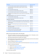
12.
Remove the display panel cable
(4)
.
13.
If it is necessary to replace the standard display hinges, remove the eight Phillips PM2.0×4.0
screws
(1)
that secure the hinges to the display panel.
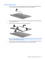
14.
Remove the display hinges
(2)
.
15.
If it is necessary to replace the standard display wireless antenna transceivers and cables, remove
the two Phillips PM2.5×4.0 screws
(1)
that secure each transceiver to the display enclosure.
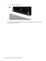
16.
Remove the wireless antenna cables from the clips
(2)
built into the display enclosure.
17.
Detach the wireless antenna transceivers
(3)
from the display enclosure.
Component replacement procedures
89