HP Dv4-1124nr HP Pavilion dv4 Entertainment PC - Maintenance and Service Guide - Page 93
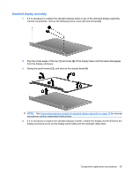
To prevent damage to the display assembly, support it before removing the screws.
 |
UPC - 884420609841
View all HP Dv4-1124nr manuals
Add to My Manuals
Save this manual to your list of manuals |
Page 93 highlights
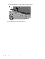
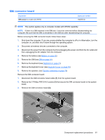
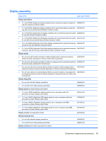
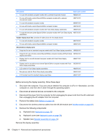
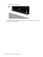
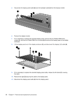
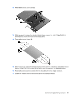
1. Locate the wireless antenna cable (1), and remove from path (2). 2. Disconnect the wireless antenna cable from the system board (3). 3. Remove the wireless antenna cable from the path (1) and disconnect it from the system board (2). CAUTION: The display assembly will be unsupported when the following screws are removed. To prevent damage to the display assembly, support it before removing the screws. 4. Remove the four Phillips PM2.5×7.0 screws (1) that secure the display assembly to the computer. Component replacement procedures 85
-
 1
1 -
2
-
3
-
4
-
5
-
6
-
7
-
8
-
9
-
10
-
11
-
12
-
13
-
14
-
15
-
16
-
17
-
18
-
19
-
20
-
21
-
22
-
23
-
24
-
25
-
26
-
27
-
28
-
29
-
30
-
31
-
32
-
33
-
34
-
35
-
36
-
37
-
38
-
39
-
40
-
41
-
42
-
43
-
44
-
45
-
46
-
47
-
48
-
49
-
50
-
51
-
52
-
53
-
54
-
55
-
56
-
57
-
58
-
59
-
60
-
61
-
62
-
63
-
64
-
65
-
66
-
67
-
68
-
69
-
70
-
71
-
72
-
73
-
74
-
75
-
76
-
77
-
78
-
79
-
80
-
81
-
82
-
83
-
84
-
85
-
86
-
87
-
 88
88 -
 89
89 -
 90
90 -
 91
91 -
 92
92 -
 93
93 -
 94
94 -
 95
95 -
 96
96 -
 97
97 -
 98
98 -
99
-
100
-
101
-
102
-
103
-
104
-
105
-
106
-
107
-
108
-
109
-
110
-
111
-
112
-
113
-
114
-
115
-
116
-
117
-
118
-
119
-
120
-
121
-
122
-
123
-
124
-
125
-
126
-
127
-
128
-
129
-
130
-
131
-
132
-
133
-
134
-
135
-
136
-
137
-
138
-
139
-
140
-
141
-
142
-
143
-
144
-
145
-
146
-
147
-
148
-
149
-
150
-
151
-
152
-
153
-
154
-
155
-
156
-
157
-
158
-
159
-
160
-
161
-
162
-
163
-
164
-
165
-
166
-
167
-
168
-
169
-
170
-
171
-
172
-
173
-
174
-
175
-
176
-
177
-
178
-
179
-
180
-
181
-
182
-
183
-
184
-
185
-
186
-
187
-
188
-
189
-
190
-
191
-
192
-
193
-
194
-
195
-
196
-
197
-
198
-
199
-
200
-
201
-
202
 |
 |
1.
Locate the wireless antenna cable
(1)
, and remove from path
(2)
.
2.
Disconnect the wireless antenna cable from the system board
(3)
.
3.
Remove the wireless antenna cable from the path
(1)
and disconnect it from the system board
(2)
.
CAUTION:
The display assembly will be unsupported when the following screws are removed.
To prevent damage to the display assembly, support it before removing the screws.
4.
Remove the four Phillips PM2.5×7.0 screws
(1)
that secure the display assembly to the computer.
Component replacement procedures
85