HP Dv5-1010us HP Pavilion dv5 Entertainment PC - Maintenance and Service Guide - Page 100
System board, Top cover see
 |
View all HP Dv5-1010us manuals
Add to My Manuals
Save this manual to your list of manuals |
Page 100 highlights
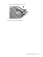
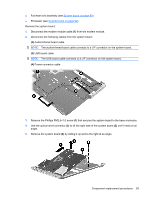
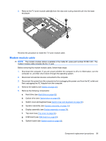
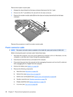
System board NOTE: All system board spare kits include replacement thermal material. Description For use only with computer models equipped with AMD processors: With RX781 Northbridge and ATI-M82-S discrete graphics subsystem memory With RS780 Northbridge and ATI-M UMA graphics subsystem memory For use only with computer models equipped with Intel processors: With PM45 Northbridge and nVidia NB9P-GS discrete graphics subsystem memory With PM45 Northbridge and nVidia NB9M-GE discrete graphics subsystem memory With GM45 Northbridge and UMA graphics subsystem memory With ICH9M Northbridge and UMA graphics subsystem memory Spare part number 482324-001 482325-001 482870-001 482867-001 482869-001 482868-001 Before removing the system board, follow these steps: 1. Shut down the computer. If you are unsure whether the computer is off or in Hibernation, turn the computer on, and then shut it down through the operating system. 2. Disconnect all external devices connected to the computer. 3. Disconnect the power from the computer by first unplugging the power cord from the AC outlet and then unplugging the AC adapter from the computer. 4. Remove the battery (see Battery on page 52). 5. Remove the following components: a. Hard drive (see Hard drive on page 62) b. Optical drive (see Optical drive on page 55) c. Switch cover (see Switch cover and keyboard on page 69) d. Speaker assembly (see Speaker assembly on page 74) e. Display assembly (see Display assembly on page 76) f. Top cover (see Top cover on page 84) When replacing the system board, be sure that the following components are removed from the defective system board and installed on the replacement system board: ● TV tuner module (see TV tuner module on page 57) ● RTC battery (see RTC battery on page 59) ● Memory modules (see Memory module on page 60) ● WLAN module (see Bluetooth module on page 75) ● Modem module (see Modem module on page 87) 92 Chapter 4 Removal and replacement procedures
-
 1
1 -
2
-
3
-
4
-
5
-
6
-
7
-
8
-
9
-
10
-
11
-
12
-
13
-
14
-
15
-
16
-
17
-
18
-
19
-
20
-
21
-
22
-
23
-
24
-
25
-
26
-
27
-
28
-
29
-
30
-
31
-
32
-
33
-
34
-
35
-
36
-
37
-
38
-
39
-
40
-
41
-
42
-
43
-
44
-
45
-
46
-
47
-
48
-
49
-
50
-
51
-
52
-
53
-
54
-
55
-
56
-
57
-
58
-
59
-
60
-
61
-
62
-
63
-
64
-
65
-
66
-
67
-
68
-
69
-
70
-
71
-
72
-
73
-
74
-
75
-
76
-
77
-
78
-
79
-
80
-
81
-
82
-
83
-
84
-
85
-
86
-
87
-
88
-
89
-
90
-
91
-
92
-
93
-
94
-
 95
95 -
 96
96 -
 97
97 -
 98
98 -
 99
99 -
 100
100 -
 101
101 -
 102
102 -
 103
103 -
 104
104 -
 105
105 -
106
-
107
-
108
-
109
-
110
-
111
-
112
-
113
-
114
-
115
-
116
-
117
-
118
-
119
-
120
-
121
-
122
-
123
-
124
-
125
-
126
-
127
-
128
-
129
-
130
-
131
-
132
-
133
-
134
-
135
-
136
-
137
-
138
-
139
-
140
-
141
-
142
-
143
-
144
-
145
-
146
-
147
-
148
-
149
-
150
-
151
-
152
-
153
-
154
-
155
-
156
-
157
-
158
-
159
-
160
-
161
-
162
-
163
-
164
-
165
-
166
-
167
-
168
-
169
-
170
-
171
-
172
-
173
 |
 |