HP Dv5-1010us HP Pavilion dv5 Entertainment PC - Maintenance and Service Guide - Page 86
Two Phillips PM2.5×7.0 screws.
 |
View all HP Dv5-1010us manuals
Add to My Manuals
Save this manual to your list of manuals |
Page 86 highlights
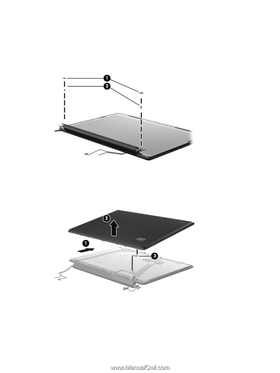
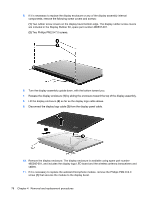
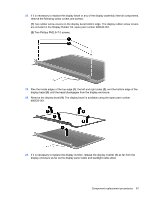
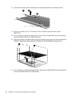
5. If it is necessary to replace the display enclosure or any of the display assembly internal components, remove the following screw covers and screws: (1) Two rubber screw covers on the display bezel bottom edge. The display rubber screw covers are included in the Display Rubber Kit, spare part number 486537-001. (2) Two Phillips PM2.5×7.0 screws. 6. Turn the display assembly upside down, with the bottom toward you. 7. Release the display enclosure (1) by sliding the enclosure toward the top of the display assembly. 8. Lift the display enclosure (2) as far as the display logo cable allows. 9. Disconnect the display logo cable (3) from the display panel cable. 10. Remove the display enclosure. The display enclosure is available using spare part number 485345-001, and includes the display logo LED board and the wireless antenna transceivers and cables. 11. If it is necessary to replace the webcam/microphone module, remove the Phillips PM2.0×4.0 screw (1) that secures the module to the display bezel. 78 Chapter 4 Removal and replacement procedures
-
 1
1 -
2
-
3
-
4
-
5
-
6
-
7
-
8
-
9
-
10
-
11
-
12
-
13
-
14
-
15
-
16
-
17
-
18
-
19
-
20
-
21
-
22
-
23
-
24
-
25
-
26
-
27
-
28
-
29
-
30
-
31
-
32
-
33
-
34
-
35
-
36
-
37
-
38
-
39
-
40
-
41
-
42
-
43
-
44
-
45
-
46
-
47
-
48
-
49
-
50
-
51
-
52
-
53
-
54
-
55
-
56
-
57
-
58
-
59
-
60
-
61
-
62
-
63
-
64
-
65
-
66
-
67
-
68
-
69
-
70
-
71
-
72
-
73
-
74
-
75
-
76
-
77
-
78
-
79
-
80
-
 81
81 -
 82
82 -
 83
83 -
 84
84 -
 85
85 -
 86
86 -
 87
87 -
 88
88 -
 89
89 -
 90
90 -
 91
91 -
92
-
93
-
94
-
95
-
96
-
97
-
98
-
99
-
100
-
101
-
102
-
103
-
104
-
105
-
106
-
107
-
108
-
109
-
110
-
111
-
112
-
113
-
114
-
115
-
116
-
117
-
118
-
119
-
120
-
121
-
122
-
123
-
124
-
125
-
126
-
127
-
128
-
129
-
130
-
131
-
132
-
133
-
134
-
135
-
136
-
137
-
138
-
139
-
140
-
141
-
142
-
143
-
144
-
145
-
146
-
147
-
148
-
149
-
150
-
151
-
152
-
153
-
154
-
155
-
156
-
157
-
158
-
159
-
160
-
161
-
162
-
163
-
164
-
165
-
166
-
167
-
168
-
169
-
170
-
171
-
172
-
173
 |
 |