HP Dv5-1010us HP Pavilion dv5 Entertainment PC - Maintenance and Service Guide - Page 101
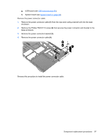
Remove the Phillips PM2.5×7.0 screw, that secures the system board to the base enclosure.
 |
View all HP Dv5-1010us manuals
Add to My Manuals
Save this manual to your list of manuals |
Page 101 highlights
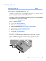
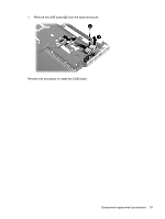
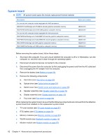
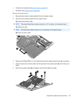
● Fan/heat sink assembly (see System board on page 92) ● Processor (see System board on page 92) Remove the system board: 1. Disconnect the modem module cable (1) from the modem module. 2. Disconnect the following cables from the system board: (2) Audio/infrared board cable NOTE: The audio/infrared board cable connects to a LIF connector on the system board. (3) USB board cable NOTE: The USB board cable connects to a LIF connector on the system board. (4) Power connector cable 3. Remove the Phillips PM2.5×7.0 screw (1) that secures the system board to the base enclosure. 4. Use the optical drive connector (2) to lift the right side of the system board (3) until it rests at an angle. 5. Remove the system board (4) by sliding it up and to the right at an angle. Component replacement procedures 93
-
 1
1 -
2
-
3
-
4
-
5
-
6
-
7
-
8
-
9
-
10
-
11
-
12
-
13
-
14
-
15
-
16
-
17
-
18
-
19
-
20
-
21
-
22
-
23
-
24
-
25
-
26
-
27
-
28
-
29
-
30
-
31
-
32
-
33
-
34
-
35
-
36
-
37
-
38
-
39
-
40
-
41
-
42
-
43
-
44
-
45
-
46
-
47
-
48
-
49
-
50
-
51
-
52
-
53
-
54
-
55
-
56
-
57
-
58
-
59
-
60
-
61
-
62
-
63
-
64
-
65
-
66
-
67
-
68
-
69
-
70
-
71
-
72
-
73
-
74
-
75
-
76
-
77
-
78
-
79
-
80
-
81
-
82
-
83
-
84
-
85
-
86
-
87
-
88
-
89
-
90
-
91
-
92
-
93
-
94
-
95
-
 96
96 -
 97
97 -
 98
98 -
 99
99 -
 100
100 -
 101
101 -
 102
102 -
 103
103 -
 104
104 -
 105
105 -
 106
106 -
107
-
108
-
109
-
110
-
111
-
112
-
113
-
114
-
115
-
116
-
117
-
118
-
119
-
120
-
121
-
122
-
123
-
124
-
125
-
126
-
127
-
128
-
129
-
130
-
131
-
132
-
133
-
134
-
135
-
136
-
137
-
138
-
139
-
140
-
141
-
142
-
143
-
144
-
145
-
146
-
147
-
148
-
149
-
150
-
151
-
152
-
153
-
154
-
155
-
156
-
157
-
158
-
159
-
160
-
161
-
162
-
163
-
164
-
165
-
166
-
167
-
168
-
169
-
170
-
171
-
172
-
173
 |
 |