HP Dv5-1010us HP Pavilion dv5 Entertainment PC - Maintenance and Service Guide - Page 89
The display bezel is available using the spare part number, Remove the display bezel
 |
View all HP Dv5-1010us manuals
Add to My Manuals
Save this manual to your list of manuals |
Page 89 highlights
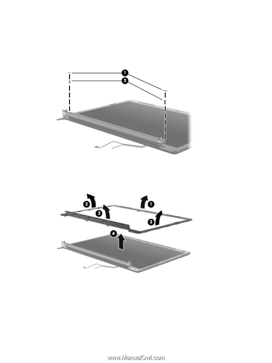
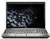
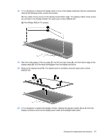
22. If it is necessary to replace the display bezel or any of the display assembly internal components, remove the following screw covers and screws: (1) Two rubber screw covers on the display bezel bottom edge. The display rubber screw covers are included in the Display Rubber Kit, spare part number 480442-001. (2) Two Phillips PM2.5×7.0 screws. 23. Flex the inside edges of the top edge (1), the left and right sides (2), and the bottom edge of the display bezel (3) until the bezel disengages from the display enclosure. 24. Remove the display bezel (4). The display bezel is available using the spare part number 486532-001. 25. If it is necessary to replace the display inverter, release the display inverter (1) as far from the display enclosure as far as the display panel cable and backlight cable allow. Component replacement procedures 81
-
 1
1 -
2
-
3
-
4
-
5
-
6
-
7
-
8
-
9
-
10
-
11
-
12
-
13
-
14
-
15
-
16
-
17
-
18
-
19
-
20
-
21
-
22
-
23
-
24
-
25
-
26
-
27
-
28
-
29
-
30
-
31
-
32
-
33
-
34
-
35
-
36
-
37
-
38
-
39
-
40
-
41
-
42
-
43
-
44
-
45
-
46
-
47
-
48
-
49
-
50
-
51
-
52
-
53
-
54
-
55
-
56
-
57
-
58
-
59
-
60
-
61
-
62
-
63
-
64
-
65
-
66
-
67
-
68
-
69
-
70
-
71
-
72
-
73
-
74
-
75
-
76
-
77
-
78
-
79
-
80
-
81
-
82
-
83
-
 84
84 -
 85
85 -
 86
86 -
 87
87 -
 88
88 -
 89
89 -
 90
90 -
 91
91 -
 92
92 -
 93
93 -
 94
94 -
95
-
96
-
97
-
98
-
99
-
100
-
101
-
102
-
103
-
104
-
105
-
106
-
107
-
108
-
109
-
110
-
111
-
112
-
113
-
114
-
115
-
116
-
117
-
118
-
119
-
120
-
121
-
122
-
123
-
124
-
125
-
126
-
127
-
128
-
129
-
130
-
131
-
132
-
133
-
134
-
135
-
136
-
137
-
138
-
139
-
140
-
141
-
142
-
143
-
144
-
145
-
146
-
147
-
148
-
149
-
150
-
151
-
152
-
153
-
154
-
155
-
156
-
157
-
158
-
159
-
160
-
161
-
162
-
163
-
164
-
165
-
166
-
167
-
168
-
169
-
170
-
171
-
172
-
173
 |
 |