HP Dv5-1010us HP Pavilion dv5 Entertainment PC - Maintenance and Service Guide - Page 80
from the LIF connector on the system board., Disconnect the LED board cable
 |
View all HP Dv5-1010us manuals
Add to My Manuals
Save this manual to your list of manuals |
Page 80 highlights
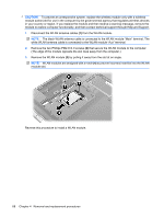
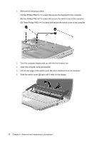
10. Release the zero insertion force (ZIF) connector (1) to which the keyboard cable is connected and disconnect the cable (2) from the system board. 11. Remove the keyboard. 12. Disconnect the power button board cable (1) from the low insertion force (LIF) connector on the system board. 13. Disconnect the LED board cable (2) from the LIF connector on the system board. 14. Remove the switch cover. Reverse this procedure to install the switch cover and keyboard. 72 Chapter 4 Removal and replacement procedures
-
 1
1 -
2
-
3
-
4
-
5
-
6
-
7
-
8
-
9
-
10
-
11
-
12
-
13
-
14
-
15
-
16
-
17
-
18
-
19
-
20
-
21
-
22
-
23
-
24
-
25
-
26
-
27
-
28
-
29
-
30
-
31
-
32
-
33
-
34
-
35
-
36
-
37
-
38
-
39
-
40
-
41
-
42
-
43
-
44
-
45
-
46
-
47
-
48
-
49
-
50
-
51
-
52
-
53
-
54
-
55
-
56
-
57
-
58
-
59
-
60
-
61
-
62
-
63
-
64
-
65
-
66
-
67
-
68
-
69
-
70
-
71
-
72
-
73
-
74
-
 75
75 -
 76
76 -
 77
77 -
 78
78 -
 79
79 -
 80
80 -
 81
81 -
 82
82 -
 83
83 -
 84
84 -
 85
85 -
86
-
87
-
88
-
89
-
90
-
91
-
92
-
93
-
94
-
95
-
96
-
97
-
98
-
99
-
100
-
101
-
102
-
103
-
104
-
105
-
106
-
107
-
108
-
109
-
110
-
111
-
112
-
113
-
114
-
115
-
116
-
117
-
118
-
119
-
120
-
121
-
122
-
123
-
124
-
125
-
126
-
127
-
128
-
129
-
130
-
131
-
132
-
133
-
134
-
135
-
136
-
137
-
138
-
139
-
140
-
141
-
142
-
143
-
144
-
145
-
146
-
147
-
148
-
149
-
150
-
151
-
152
-
153
-
154
-
155
-
156
-
157
-
158
-
159
-
160
-
161
-
162
-
163
-
164
-
165
-
166
-
167
-
168
-
169
-
170
-
171
-
172
-
173
 |
 |
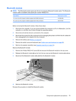
10.
Release the zero insertion force (ZIF) connector
(1)
to which the keyboard cable is connected and
disconnect the cable
(2)
from the system board.
11.
Remove the keyboard.
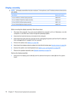
12.
Disconnect the power button board cable
(1)
from the low insertion force (LIF) connector on the
system board.
13.
Disconnect the LED board cable
(2)
from the LIF connector on the system board.
14.
Remove the switch cover.
Reverse this procedure to install the switch cover and keyboard.
72
Chapter 4
Removal and replacement procedures