HP Integrity Superdome 2 8/16 HP Integrity Superdome 2 Onboard Administrator U - Page 124
XFM Bay Information - Bay screen, UID State
 |
View all HP Integrity Superdome 2 8/16 manuals
Add to My Manuals
Save this manual to your list of manuals |
Page 124 highlights
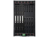
The check box in the first column on the top row toggles all check boxes on or off for all XFMs. This feature is useful if you want to toggle the UID state for all XFMs at the same time. Otherwise, the first column contains checkboxes that can be used to select individual XFMs. After the appropriate interconnects are selected, the UID state drop-down can be selected to toggle the UID state. Item Description Check box Select the check box next to the bay or bays where you want to apply the UID State features. Bay Bay in the enclosure of the corresponding XFM. This box displays only populated bays. Empty bays are not displayed in this table. Status Overall status of the XFM. Possible values are Unknown, OK, Degraded, and Failed. UID Status of the UID on the XFM. Possible values are On (blue) or Off (gray). Power State Power state of the XFM. Possible values are On or Off. Engineering Date Code Manufacturing information about the XFM. Part Number Part number of the XFM used to order replacement parts of the same type. Product Name Common descriptive name for the XFM. Information on this page is current as of last download. Click the Refresh button to view updated information. UID State The UID State menu is used to set the UID LED on the XFM. Turning on the UID LED assists in locating a specific XFM within an enclosure. These LEDs can be turned on or off one at a time or as groups depending on the checkboxes. XFM Bay Information - Bay screen The XFM Bay screen displays information about the bays where XFMs can be placed. 124 Configuring HP Integrity Superdome 2 compute enclosures and enclosure devices
-
 1
1 -
2
-
3
-
4
-
5
-
6
-
7
-
8
-
9
-
10
-
11
-
12
-
13
-
14
-
15
-
16
-
17
-
18
-
19
-
20
-
21
-
22
-
23
-
24
-
25
-
26
-
27
-
28
-
29
-
30
-
31
-
32
-
33
-
34
-
35
-
36
-
37
-
38
-
39
-
40
-
41
-
42
-
43
-
44
-
45
-
46
-
47
-
48
-
49
-
50
-
51
-
52
-
53
-
54
-
55
-
56
-
57
-
58
-
59
-
60
-
61
-
62
-
63
-
64
-
65
-
66
-
67
-
68
-
69
-
70
-
71
-
72
-
73
-
74
-
75
-
76
-
77
-
78
-
79
-
80
-
81
-
82
-
83
-
84
-
85
-
86
-
87
-
88
-
89
-
90
-
91
-
92
-
93
-
94
-
95
-
96
-
97
-
98
-
99
-
100
-
101
-
102
-
103
-
104
-
105
-
106
-
107
-
108
-
109
-
110
-
111
-
112
-
113
-
114
-
115
-
116
-
117
-
118
-
 119
119 -
 120
120 -
 121
121 -
 122
122 -
 123
123 -
 124
124 -
 125
125 -
 126
126 -
 127
127 -
 128
128 -
 129
129 -
130
-
131
-
132
-
133
-
134
-
135
-
136
-
137
-
138
-
139
-
140
-
141
-
142
-
143
-
144
-
145
-
146
-
147
-
148
-
149
-
150
-
151
-
152
-
153
-
154
-
155
-
156
-
157
-
158
-
159
-
160
-
161
-
162
-
163
-
164
-
165
-
166
-
167
-
168
-
169
-
170
-
171
-
172
-
173
-
174
-
175
-
176
-
177
-
178
-
179
-
180
-
181
-
182
-
183
-
184
-
185
-
186
-
187
-
188
-
189
-
190
-
191
-
192
-
193
-
194
-
195
-
196
-
197
 |
 |
