HP J4819A User Manual - Page 13
LEDs, Introducing the ProCurve Switch 5300xl Series, State, Meaning
 |
View all HP J4819A manuals
Add to My Manuals
Save this manual to your list of manuals |
Page 13 highlights
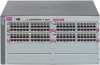
Introducing the ProCurve Switch 5300xl Series Introducing the ProCurve Switch 5300xl Series Front of the Switch LEDs As described in the next two tables, there are LEDs on the switch chassis and on the switch modules that keep you informed of the status of the switch and the network connections. Table 1-1. Switch Chassis LEDs LEDs Power (green) Fault (orange) State On Off Off Flashing† On Self Test Off (green) On Flashing† Status/Fan (green) On Flashing† Status/Power On (green - numbers corresponding to the power Off supply positions) Flashing† Meaning The switch is receiving power. The switch is NOT receiving power. The normal state; indicates that there are no fault conditions on the switch. A fault has occurred on the switch, one of the switch modules, an individual port, a power supply, or a fan. The Status LED for the module or other device with the fault will flash simultaneously. On briefly at the beginning of switch self test after the switch is powered on or reset. If on for a prolonged time, the switch has encountered a fatal hardware failure, or has failed its self test. See chapter 4, "Troubleshooting" for more information. The normal operational state; the switch is not undergoing self test. The switch self test and initialization are in progress after you have power cycled or reset the switch. The switch is not operational until this LED goes off. The Self Test LED also comes on briefly when you "hot swap" a module into the switch and the module is automatically self tested. A component of the switch has failed its self test. The Status LED for that component, for example a switch module, and the switch Fault LED will flash simultaneously. The cooling fans are operating normally. One or more of the cooling fans have failed. The switch Fault LED will be flashing simultaneously. A power supply is installed in the position in the back of the switch corresponding to the number, and the supply is plugged in to an active AC power source. As shipped, the switch has a single power supply in position 1. A power supply is not installed in the position corresponding to the number. The power supply installed in the position corresponding to the number is not plugged in to an active AC power source, or has experienced a fault. The switch Fault LED will be flashing simultaneously. 1-5
-
 1
1 -
2
-
3
-
4
-
5
-
6
-
7
-
 8
8 -
 9
9 -
 10
10 -
 11
11 -
 12
12 -
 13
13 -
 14
14 -
 15
15 -
 16
16 -
 17
17 -
 18
18 -
19
-
20
-
21
-
22
-
23
-
24
-
25
-
26
-
27
-
28
-
29
-
30
-
31
-
32
-
33
-
34
-
35
-
36
-
37
-
38
-
39
-
40
-
41
-
42
-
43
-
44
-
45
-
46
-
47
-
48
-
49
-
50
-
51
-
52
-
53
-
54
-
55
-
56
-
57
-
58
-
59
-
60
-
61
-
62
-
63
-
64
-
65
-
66
-
67
-
68
-
69
-
70
-
71
-
72
-
73
-
74
-
75
-
76
-
77
-
78
-
79
-
80
-
81
-
82
-
83
-
84
-
85
-
86
-
87
-
88
-
89
-
90
-
91
-
92
-
93
-
94
-
95
-
96
-
97
-
98
-
99
-
100
-
101
-
102
-
103
-
104
-
105
-
106
-
107
-
108
 |
 |
