HP J4819A User Manual - Page 15
LED Mode Select Button and Indicator LEDs, Introducing the ProCurve, Switch 5300xl Series,
 |
View all HP J4819A manuals
Add to My Manuals
Save this manual to your list of manuals |
Page 15 highlights
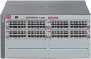
Introducing the ProCurve Switch 5300xl Series Introducing the ProCurve Switch 5300xl Series Front of the Switch LED Mode Select Button and Indicator LEDs To optimize the amount of information that can be displayed for each of the switch ports, the Switch 5300xl Series use a Mode LED for each port. The operation of this LED is controlled by the LED Mode Select button on the switch chassis, and the current selection is indicated by the mode indicator LEDs near the button. Press the button to change from one mode to the next. LED Mode Select button and indicator LEDs Mode LEDs (one for each port) Status 12ABCD an Power Modules Act FDx Max ! LED Mode Select Use xl modules only A xl procurve xl module J4820A C Figure 1-7. Example Mode Select button and Mode LEDs ■ If the Activity Act indicator LED is lit, each port Mode LED displays activity information for the port-it flickers as network traffic is received and transmitted through the port. ■ If the Full Duplex FDx indicator LED is lit, the port Mode LEDs light for those ports that are operating in full duplex. ■ If the maximum speed Max indicator LED is lit, the port Mode LEDs light for those ports that are operating at their maximum possible link speed, for example 1000 Mbps on a 100/1000-T port. ■ If the attention ! indicator LED is lit, each Mode LED lights briefly for each network event that might require operator attention, for example, late collisions or CRC errors. See chapter 4, "Troubleshooting" for more information. 1-7
-
 1
1 -
2
-
3
-
4
-
5
-
6
-
7
-
8
-
9
-
 10
10 -
 11
11 -
 12
12 -
 13
13 -
 14
14 -
 15
15 -
 16
16 -
 17
17 -
 18
18 -
 19
19 -
 20
20 -
21
-
22
-
23
-
24
-
25
-
26
-
27
-
28
-
29
-
30
-
31
-
32
-
33
-
34
-
35
-
36
-
37
-
38
-
39
-
40
-
41
-
42
-
43
-
44
-
45
-
46
-
47
-
48
-
49
-
50
-
51
-
52
-
53
-
54
-
55
-
56
-
57
-
58
-
59
-
60
-
61
-
62
-
63
-
64
-
65
-
66
-
67
-
68
-
69
-
70
-
71
-
72
-
73
-
74
-
75
-
76
-
77
-
78
-
79
-
80
-
81
-
82
-
83
-
84
-
85
-
86
-
87
-
88
-
89
-
90
-
91
-
92
-
93
-
94
-
95
-
96
-
97
-
98
-
99
-
100
-
101
-
102
-
103
-
104
-
105
-
106
-
107
-
108
 |
 |
