HP J8698A User Manual - Page 40
LED Behavior:, Installing the Series 5400zl, Switches, Switch Fault, Module
 |
View all HP J8698A manuals
Add to My Manuals
Save this manual to your list of manuals |
Page 40 highlights
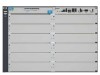
Installing the Series 5400zl Switches Installation Procedures Switch Fault LED Switch Module LEDs: Link and Mode LEDs for each port Switch Chassis LEDs Installing the Series 5400zl Switches Figure 2-6. Switch Fault, Module, and Chassis LEDs When the switch is powered on, it performs its diagnostic self test. The entire download, initialization, and self test process can take up to 2 minutes for a fully loaded chassis, depending on the number and type of modules installed in the switch. LED Behavior: During the self test: ■ Initially, Power, Fault, Locator, and all the switch chassis LEDs are on. Then, after approximately 30 seconds, all the module LEDs go on as the modules receive power and code is downloaded to them, the Fault LED goes off, and the chassis LEDs turn orange and then go off except Test, Fan, and Power, which turn green. ■ When the download of code to the modules is completed, the module LEDs go off. You may see each port LED go on briefly, in sequence, as the port is tested. ■ For the duration of the self test, the Test LED stays on. When the test completes successfully: ■ The Power LED stays on, and the Status LEDs on the switch chassis stay on for the devices installed: one for each switch module installed, one for each power supply installed, and one for all the fans. ■ The Fault, Locator, and Test LEDs are off. ■ The port LEDs on the switch modules go into their normal operational mode: 2-16
-
 1
1 -
2
-
3
-
4
-
5
-
6
-
7
-
8
-
9
-
10
-
11
-
12
-
13
-
14
-
15
-
16
-
17
-
18
-
19
-
20
-
21
-
22
-
23
-
24
-
25
-
26
-
27
-
28
-
29
-
30
-
31
-
32
-
33
-
34
-
 35
35 -
 36
36 -
 37
37 -
 38
38 -
 39
39 -
 40
40 -
 41
41 -
 42
42 -
 43
43 -
 44
44 -
 45
45 -
46
-
47
-
48
-
49
-
50
-
51
-
52
-
53
-
54
-
55
-
56
-
57
-
58
-
59
-
60
-
61
-
62
-
63
-
64
-
65
-
66
-
67
-
68
-
69
-
70
-
71
-
72
-
73
-
74
-
75
-
76
-
77
-
78
-
79
-
80
-
81
-
82
-
83
-
84
-
85
-
86
-
87
-
88
-
89
-
90
-
91
-
92
-
93
-
94
-
95
-
96
-
97
-
98
-
99
-
100
-
101
-
102
-
103
-
104
-
105
-
106
-
107
-
108
-
109
-
110
-
111
-
112
-
113
-
114
-
115
-
116
-
117
-
118
 |
 |
